
Page 565 - APPLIED PROCESS DESIGN FOR CHEMICAL AND PETROCHEMICAL PLANTS, Volume 1, 3rd Edition
P. 565
Applied Process Design 531
Wind---+-
• I
I
'
It.y
I
+
I
I
I
I
I H' D
H
I
I
I
I
t
�----R'----
..-------R-----
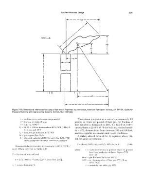
Figure 7-73. Dimensional references for sizing a flare stack. Reprinted by permission, American Petroleum Institute, API RP-521, Guide for
Pressure Relieving and Depressuring Systems, 3rd Ed., Nov. 1990 [33].
n = mol fraction combustion compound(s) When steam is injected at a rate of approximately 0.3
f = fraction of radiated heat pounds of steam per pound of flare gas, the fraction of
f = 0.20 (hc/900] 11 2 heat radiated is decreased by 20%. 't is based on hydro-
he = 50 M + 100 for hydrocarbons BTU/SCF (LHV) @ carbon flame at 2240°F, 80 °F dry bulb air, relative humid-
14. 7 psia and 60°F ity> 10%, distance from flame between 100 and 500 feet,
he = :Enhc for gas mixtures, BTU/SCF and is acceptable to estimate under wide conditions.
W = gas/vapors flow, lb/hr A slightly altered form of the Dr equation above [61,
K = allowable radiation, BTU/hr/sq ft (See Table 7-32) 62] for spherical radiation:
Select acceptable value for "conditions assumed"
I= (flow) (NHV) (E)/(41tDi), BTU/hr/sq ft (7-86)
Reasonable heat intensity, K, values are 1,500 BTU/hr/
sq ft. When referred to Table 7-32 where 1 = radiation iruensity at point of object on ground
level from midpoint of flame, Figures 7-73
F = fraction of heat radiated and 7-74
Flow = gas flow rate, lb/hr (or SCFH)
1
r = 0.79 (100/r) 1 16 (100/DF) 1 16, from Ref. [33C]. NI-IV = net heating value of flare gas, BTU/lb or,
1
(BTU/SCF)
r 1 = relative humidity, % E = emissivity (see table, pg. 525)