
Page 564 - APPLIED PROCESS DESIGN FOR CHEMICAL AND PETROCHEMICAL PLANTS, Volume 1, 3rd Edition
P. 564
530 Applied Process Design for Chemical and Petrochemical Plants
103
,, -
* �
,!\ ;. ""x
j �� I,
1 I/ [
� Iii �
>- " �
c
lll 102
en
c
� - l.w. LEGEND:
u •
c
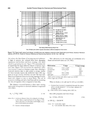
;. .. L/ Fuel gas (20-lnch stack)
5 0 Algerian gas well
en
..
c
� . ,,. i,.,,- .... /:,. Catalytic reformer-recycle
gas (24-inch stack)
E o Catalytic reformer-reactor
Ill
a: effluent gas (24-inch stack)
c Dehydrogenation unit
10 1 (12-lnch stack)
x Hydrogen (31-inch stack)
* Hydrogen (30-inch stack)
10 7 108 11)8 1010 10 11
Heat release, Bfltish thermal units per hour
Note: Multiple points indicate separate observations or different assumptions of heat content.
Figure 7-72. Flame length versus heat release: industrial sizes and releases (customary units). Reprinted by permission, American Petroleum
Institute, API RP-521, Guide for Pressure Relieving and Depressuring Systems, 3rd Ed., Nov. 1990 [33].
(b) to keep the flare flame of burning material sufficient- This references to the total heat of combustion of a
ly high to prevent the radiated heat from damaging flame and selected values are [57, 33C]:
equipment and facilities and from creating a life safety
hazard to ground personnel. Figure 7- 75 summarizes the
accepted data for heat radiation related to human expo- Hydrocarbon Frange F range average
sure Lime. Figure 7-76 summarizes the maximum radia- Methane 0.10 LO 0.20* 0.15
tion intensity related to a human escape time, allowing a Natural Gas 0.19to0.23 0.21
5-second reaction time to take action to escape, before Propane 0.33**
the heat intensity injures the individual. Kent [60] sug- Butane 0.21 to 0.30 0.28
gests an escape velocity of 20 feet/second. The heat radi- Hydrogen 0.10 to 0.17 0.15
ation is an important factor in locating/spacing of equip- *0.20 used for methane with carbon weight ratio of 0.333.
ment with respect to one or more flares. The use of **With weight ratio of 0.222.
protective clothing and safety hard hats aids in extending
the time of exposure when compared to bare skin. When in doubt, to be safe use 0.4 [57] or 1.0 [33C].
The distance required between a flare stack venting 'r = fraction heat intensity k transmitted through the atmos-
and a point of exposure to thermal radiation is expressed phere, usually assumed = 1.0 (see later equation for
[57] [33C]: modifying) [33c].
Qr= heat release (lower heating valve), BTU/hr
D r = � 'r FQ./ ( 41tK) (7- 84) Kent [60) proposes total heat release:
Q, = W Lnhc (379/M) (7-85)
where DF = minimum distance from the midpoint of a flame
to the object, at ground level, ft (see Figure 7-73) or (59) Q = 20,000 W
0
(Note that this is not the flare stack height, but a
part of calculation procedure)
where M = molecular weight
F = fraction of heat radiated he= net calorific heat value, BTU/SCF