
Page 563 - APPLIED PROCESS DESIGN FOR CHEMICAL AND PETROCHEMICAL PLANTS, Volume 1, 3rd Edition
P. 563
Applied Process Design 529
This calculation is based on a steam-C02 weight ratio of
HRC: NAO's Ring-,cund·Center Smokeless Flare
approximately 0. 7 [33A, Par 5.4.3.2.11.
These should be sized for conditions under which they
Stemn. Compressed Air Free Floating
/ or Power-Gas Windshield will operate smokelessly,
Injection Via With Complete
/.
Removable Jet Floor Plate
Flame Length f 33c]
'
Mi,"No..te
Heat liberated or released by flame, Qr= (W) (He) (7-81)
where Qr= heat released by flame, BTU/hr
Fiore Pilot Whc = W = gas/vapor flow rate, lb/hr
With Individuctl He = heal of combustion of gas/vapor, BTU/lb
Windshield
Note: For many hydrocarbon-air mixtures, the value of He
ranges 20,000 to 22,000 BTU /lb.
Monolithic
Uni-Pour' Referring to Figure 7-72 at the calculated heat release,
Lining He, read the flame length, and refer to dimensional dia-
gram for flame plume from a stack, Figure 7-73.
Flame Distortion [33c} Caused by Wind Velocity
Referring to Figure 7-74, the name distortion is determined as
Center Steam. L'lx or L'ly . Calculate UJ. using the "d" determined for the sel-
Compressed Air L L
or Power Gae ected Mach No. in earlier paragraph.
Injecticn
U wind velocity
(7- 82)
U .i flare tip velocity
U = (flow)/( nd 4), ft/sec (7- 83)
2/
j
Flow, F 1 = (W/3600) (379.l/MW) [460+°F/520], cu ft/sec
based on 60°F and l4.7 psia, and 359 cu ft/mo!
U 00 = lateral wind velocity, ft/sec
Uj = exit gas velocity from stack, ft/sec
°F = flowing temperature
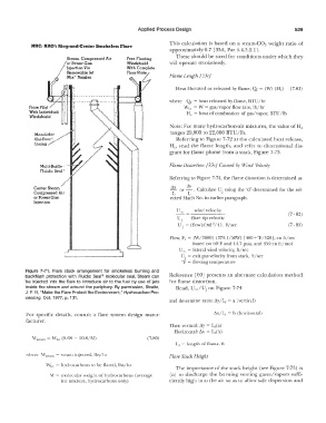
Figure 7- 71. Flare stack arrangement for smokeless burning and
backflash protection with Fluidic Seal® molecular seal. Steam can Reference [60] presents an alternate calculation method
be injected into the flare to introduce air to the fuel by use of jets for flame distortion.
inside the stream and around the periphery. By permission, Straitz, Read, U /Uj on Figure 7-74
00
J. F. Ill, "Make the Flare Protect the Environment," Hydrocarbon Pro-
cessing, Oct. 1977, p. 131.
and determine ratio: L'ly/Lr = a (vertical)
For specific details, consult a flare system design man u- L'1x/L 1 = b (horizontal)
facturer,
Then vertical: L'ly = Lr(a)
Horizontal: L'lx = Lr(b)
Wsieam = Whe (0.68 - 10.8/M) (7-80)
Lr= length of flame, fl
where \·V,ream = steam injected, lbs/hr Flare Stack Height
\Vhe = hydrocarbons to be flared, lbs/hr
The importance of the stack height (see Figure 7-73) is
M = molecular weight of hydrocarbons (average (a) to discharge the burning venting gases/vapors suffi-
for mixture, hydrocarbons only) ciently high into the air so as to allow safe dispersion and