Page 568 - APPLIED PROCESS DESIGN FOR CHEMICAL AND PETROCHEMICAL PLANTS, Volume 1, 3rd Edition
P. 568

534                       Applied Process Design for Chemical and  Petrochemical  Plants


                                 Lt,a                                     t  llt/c
                                                                    � -.)   Ye
                                                                    I   \
                                                                    :.- \
                                                                          \
                                                                           \  R
                                                                            \
               H                                                             \
                                                                              \
                                                                               \                     H
                                                                                \                            Worst
                                                                                 \                  � Position
                                                                                  \      _  __.__._.....__

                                                                """---x-�-�

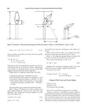
            Figure 7-77.  Diagrams for alternate flare stack designs of Straitz.  By permission, Straitz, J.  F.  Ill and Altube,  R.  J., NAO,  Inc.  [62].


                                                                  L'iy  and  Ax  from  previous  calculations  under  Ilame  dis-
              Distance, R =  �   (X-  Xe  ) + (H + Ye  ) 2   (7 - 91)
                                   2
                                                                  tortion
                                                                    Refer to Table  7-32 and select the "condition" for radi-
            Worst condition of gas  flow and wind velocities,  vertically   ation level, K, and ground distance, R,  from stack.
            below flame center:                                     Solve  for  R'  using  the  ground  distance  selected,  R,
                                                                  from stack,  and use the L'ix  previously calculated.
            then  R  =  H  +  Ye                                    Then,  determined height of stack,  H,  by
                 H  =  R  - (Lr/3)  (cos 0)
                 0  =  tan  -  l  (V,vind/V  gas  C,Ul)
                                                                    02  =  (R')2 +  (H')2                      (7-94)
            This assumes  that the flame length stays  the same for any   Substitute  the  previously  calculated  value  of the  dis-
            wind velocity  that is not rigidly  true.  With  a wind greater   tance from  center of flame to grade,  D  and also R'.
            than 60 miles/hr,  the flame tends to shorten.  Straitz  [62]
            suggests  that practically this can be neglected.       First solve for H',  then
              Design values for radiation levels usually used  [62]:
                                                                    H  (height of stack)  =  H' - 1/2 (tiy)
               1. Equipment protection:  3,000 BTU/hr/sq ft                           (previously calculated)   (7 - 95)
               2.  Personnel, short time exposure:  1,500 BTU  /hr  /sq ft
               3.  Personnel, continuous exposure:  440 BTU/hr/sq ft
              4.  Solar radiation adds to the exposure, so on sunny days,   Purging of Flare Stacks and Vessels/Piping
                 continuous  personnel  exposure:  200  -  300  BTU  I
                 hr/sq ft                                           • Vacuum cycle
                                                                    • Pressure cycle
              Determine flare stack height above ground  (grade):   • Continuous, flow through
              Refer to Figure 7-73. Based on the mach velocity of the
            vapor/gases  leaving  the  top  tip  of the  flare  stack  (see   There are several different approaches  to  purging:
            Equation  7-76),  determine  the  mach  number,  e.g.,  0.2,   Purging  a  system  of flammable  gas/vapor  mixtures
            then from Figure  7-73:                               generally involves adding an  inert gas such as  nitrogen to
                                                                  the system.  Sometimes the volumes of nitrogen are  large,
            where H' =  I-I  +  J4  (tiy)                 (7-92)   but it is still less expensive than most other nonflammable
                                                                  gas  (even  CO  and  C02  have  to  be  used  cautiously)  and
            and R' = R  - �  (Ax)                         (7-93)   certainly air cannot be used because it introduces oxygen
   563   564   565   566   567   568   569   570   571   572   573