
Page 567 - APPLIED PROCESS DESIGN FOR CHEMICAL AND PETROCHEMICAL PLANTS, Volume 1, 3rd Edition
P. 567
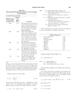
Applied Process Design                                    533

                               Table 7-32                        where    H  =  height of flare stack, ft,  Figure 7-73
           Recommended Design Flare Radiation Levels Including            L  =  height of flame  (length of flame from  top of
                             Solar Radiation                                  stack Lo flame tip), fl
                                                                      D  =  X =  radial  distance from flame core  (center)  to
           Permissible Design Level (K)                                       grade,  fl
                          Kilowatts                                    R =  y =  radial distance from base of stack,  ft,  Lo grade
           British Thermal   per                                              intersection with D
           Units per Hour   Square                                        tc  =  time interval for escape,  sec
           per Square Foot   Meter          Conditions                         Note:  For safety,  personnel  and equipment
                 �����--���������������-
               5000        15.77   Heat intensity on structures and            should be outside the "y" distance.
                                    in areas where operators are  not     R  = distance from flame center to  point X on
                                    likely  to be performing duties           ground (see Figure  7-77)
                                   and where sheller from  radiant
                                    heat is available  (for example,   This has been shown to be quite  accurate for distances
                                    behind equipment)           as close to  the flame as one flame length  [61].
               3000         9.46   Value of Kat design flare
                                    release at any location to which
                                    people have access  (for exam-               Emissivity Values [621
                                    ple,  al grade below the flare or
                                    a service platform of a  nearby    Carbon Monoxide                0.075
                                    tower); exposure should be lim-    Hydrogen                       0.075
                                    ited  to a  few seconds,  sufficient   Hydrogen  Sulfide          0.070
                                   for escape only                     Ammonia                        0.070
               2000         6.31   Heal intensity in areas where       Methane                        0.10
                                   emergency actions  lasting up to    Propane                        0.11
                                    1  minute may  be required by      Butane                         0.12
                                   personnel without shielding but     Ethylene                       0.12
                                   with appropriate clothing           Propylene                      0.13
               1500         4.73   Heal intensity  in areas where      Maximum                        0.13
                                   emergency actions lasting sever-
                                   al minutes  may be required by
                                   personnel without shielding but   Length  of Flame  [62]  See Figure  7-77
                                   with appropriate clothing
                500         l.58   Value of Kat design flare
                                   release at any location where   Lr= 10  (D)  (�P,/55) 1/ 2                (7-89)
                                   personnel  are continuously
                                   exposed
                                                                where   Le  =  length  of  flame,  ft
           Note:                                                        D  = flare  tip diameter,  in.
           On  towers or other elevated structures where  rapid escape  is not possi-   �P,  =  pressure  drop at the tip,  in.  of  water
           ble,  ladders  must be  provided  on  the side  away  from  the  flare,  so  the
           structure can provide some shielding when K is greater than 2000 British
           thermal units per hour per square  foot (6.31  kilowatts per square meter).   This gives  flame length  for conditions other than max-
           Reprinted by permission, AP! RP-521, Guide  for Pressure Relieving and Depres-   imum flow.
           surrng Systems,  3rd  E.d., Nov.  1990, American Petroleum Institute  [33].
                                                                   The center of the flame is assumed to be  located a dis-
                                                                 tance  of one-third  the  length  of the  flame  from  the  tip,
             Height of stack for still air [60]:                Lr/3  [62]. The flame  angle  is  the vector addition  of the
                                                                wind velocity  and the gas  exit velocity.

                                                       (7  - 87)
                                                                   V  cxn  '  gas exit velocity=  550 �   �p /  55  ,  ft/sec   (7-90)
           The shortest stack  exists  when  qM  =  3,300  BTU  /hr sq  ft   From  Figure  7-77
           (Figure  7-76).  The  limiting  radial  distance  from  the
           flame,  allowing for speed  of escape of 20 fl/sec is  [60]:
                                                                   Xe  =  (Lr/3)  (sin  8)

             y  =  20  t 0  =  [x 2  - H  (H +  L)]o.s   (7-88)    Ye= (Lr/3)  (cos 8)