
Page 121 - Installation Manual - GenII DTS
P. 121
Accessories
1. Disconnect both battery cables.
! CAUTION
Avoid injury or product damage. Obstructions, such as braces and wiring, may be unseen when looking at the front of the
dashboard. Before drilling or cutting any holes in the dashboard, check the area behind the dashboard for obstructions. Do
not drill or cut when obstructions are present.
IMPORTANT: To ensure that water does not collect at the key switch and drains from the housing, install the key switch a
minimum of 10 degrees from vertical.
2. Select a location for the key switch on the dashboard:
• without obstructions behind the dashboard
• within harness length limits
• that will orient the switch a minimum of 10 degrees from a vertical or upright position
• that will position the switch with enough clearance between the components to install bezels, if equipped
3. If the dashboard is fiberglass, apply masking tape to the area that is to be drilled or cut to help prevent the dashboard from
cracking.
4. If the dashboard is vinyl covered, remove the vinyl from the area to be drilled or cut to keep the vinyl from tearing.
3‑Position Key Switch Mounting
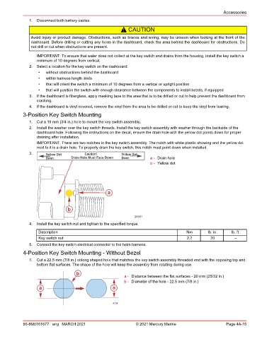
1. Cut a 19 mm (3/4 in.) hole to mount the key switch assembly.
2. Install the washer over the key switch threads. Install the key switch assembly with washer through the backside of the
dashboard hole. Following the instructions on the decal, ensure the drain hole with the yellow dot points down for proper
draining after installation.
IMPORTANT: There are two notches in the key switch assembly. The notch with white plastic showing and the yellow dot
next to it is a drain hole. To properly drain the key switch, this notch must point down when installed.
3. Yellow Dot Caution! Yellow Dot
Down Drain Hole Must Face Down Down a - Drain hole
b - Yellow dot
a
b
26591
4. Install the key switch nut and tighten to the specified torque.
Description Nm lb. in. lb. ft.
Key switch nut 2.2 20 –
5. Connect the key switch electrical connector to the helm harness.
4‑Position Key Switch Mounting ‑ Without Bezel
1. Cut a 22.5 mm (7/8 in.) oblong shaped hole that matches the key switch assembly threaded end with the opposing top and
bottom flat surfaces. The shape of the hole will keep the assembly from rotating during use.
b
a - Distance between the flat surfaces ‑ 20 mm (25/32 in.)
b - Diameter of the hole ‑ 22.5 mm (7/8 in.)
a a
4734
90-8M0161677 eng MARCH 2021 © 2021 Mercury Marine Page 4A-15