
Page 120 - Installation Manual - GenII DTS
P. 120
Accessories
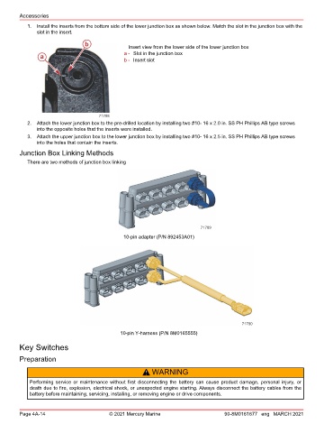
1. Install the inserts from the bottom side of the lower junction box as shown below. Match the slot in the junction box with the
slot in the insert.
b Insert view from the lower side of the lower junction box
a - Slot in the junction box
a
b - Insert slot
71788
2. Attach the lower junction box to the pre‑drilled location by installing two #10‑ 16 x 2.0 in. SS PH Phillips AB type screws
into the opposite holes that the inserts were installed.
3. Attach the upper junction box to the lower junction box by installing two #10‑ 16 x 2.5 in. SS PH Phillips AB type screws
into the holes that contain the inserts.
Junction Box Linking Methods
There are two methods of junction box linking
71789
10-pin adapter (P/N 892453A01)
71790
10-pin Y-harness (P/N 8M0165555)
Key Switches
Preparation
! WARNING
Performing service or maintenance without first disconnecting the battery can cause product damage, personal injury, or
death due to fire, explosion, electrical shock, or unexpected engine starting. Always disconnect the battery cables from the
battery before maintaining, servicing, installing, or removing engine or drive components.
Page 4A-14 © 2021 Mercury Marine 90-8M0161677 eng MARCH 2021