
Page 122 - Installation Manual - GenII DTS
P. 122
Accessories
2. Install one nut onto the key switch assembly with the flat flange of the nut toward the key end of the switch. Thread this nut
on as needed until the key switch will extend through the dashboard with enough threads exposed for the second nut to be
installed.
IMPORTANT: There are two notches in the key switch assembly. The notch with white plastic showing and the yellow dot
next to it is a drain hole. To properly drain the key switch, this notch must point down when installed.
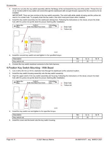
3. Install the key switch assembly into the dashboard oblong hole. Following the instructions on the decal, ensure the drain
hole with the yellow dot points down for proper draining after installation.
Yellow Dot Caution! Yellow Dot
Down Drain Hole Must Face Down Down a - Drain hole
b - Yellow dot
a
b
26591
4. Install the second key switch nut and tighten to the specified torque.
Description Nm lb. in. lb. ft.
Key switch nut 2.2 20 –
5. Connect the key switch electrical connector to the helm harness.
4‑Position Key Switch Mounting ‑ With Bezel
1. Cut or drill a 54 mm (2‑1/8 in.) diameter hole through the dashboard at the selected location.
2. Install the key switch housing assembly onto the key switch assembly.
3. Align the upper notch of the key switch assembly and housing. Following the instructions on the decal, ensure the drain
hole with the yellow dot points down for proper draining after installation.
Yellow Dot Caution! Yellow Dot
Down Drain Hole Must Face Down Down a - Drain hole
b - Yellow dot
a
b
26591
4. Install the key switch nut and tighten to the specified torque.
Description Nm lb. in. lb. ft.
Key switch nut 2.2 20 –
5. Install the cover and the bezel onto the key switch housing.
Page 4A-16 © 2021 Mercury Marine 90-8M0161677 eng MARCH 2021