
Page 47 - Installation Manual - GenII DTS
P. 47
Legacy Controls
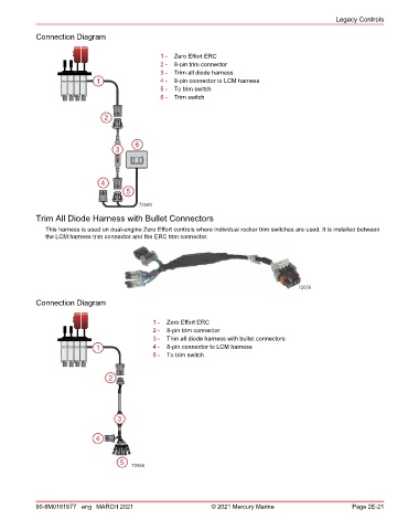
Connection Diagram
1 - Zero Effort ERC
2 - 8‑pin trim connector
3 - Trim all diode harness
1 4 - 8‑pin connector to LCM harness
5 - To trim switch
6 - Trim switch
2
6
3
4
5
72589
Trim All Diode Harness with Bullet Connectors
This harness is used on dual‑engine Zero Effort controls where individual rocker trim switches are used. It is installed between
the LCM harness trim connector and the ERC trim connector.
72556
Connection Diagram
1 - Zero Effort ERC
2 - 8‑pin trim connector
3 - Trim all diode harness with bullet connectors
1 4 - 8‑pin connector to LCM harness
5 - To trim switch
2
3
4
5 72588
90-8M0161677 eng MARCH 2021 © 2021 Mercury Marine Page 2E-21