
Page 214 - Fisika Terapan for Engineers and Scientists
P. 214
414 CHAPTER 13 Dynamics of a Rigid Body
PHYSICS IN PRACTICE THE GYROCOMPASS
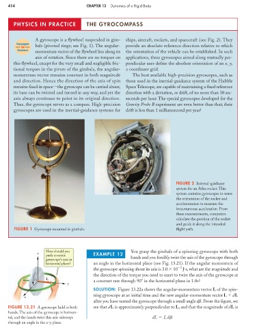
A gyroscope is a flywheel suspended in gim- ships, aircraft, rockets, and spacecraft (see Fig. 2). They
Concepts
in bals (pivoted rings; see Fig. 1). The angular- provide an absolute reference direction relative to which
Context
momentum vector of the flywheel lies along its the orientation of the vehicle can be established. In such
axis of rotation. Since there are no torques on applications, three gyroscopes aimed along mutually per-
this flywheel, except for the very small and negligible fric- pendicular axes define the absolute orientation of an x, y,
tional torques in the pivots of the gimbals, the angular- z coordinate grid.
momentum vector remains constant in both magnitude The best available high-precision gyroscopes, such as
and direction. Hence the direction of the axis of spin those used in the inertial-guidance system of the Hubble
remains fixed in space—the gyroscope can be carried about, Space Telescope, are capable of maintaining a fixed reference
its base can be twisted and turned in any way, and yet the direction with a deviation, or drift, of no more than 10 arc-
axis always continues to point in its original direction. seconds per hour. The special gyroscopes developed for the
Thus, the gyroscope serves as a compass. High-precision Gravity Probe B experiment are even better than that; their
gyroscopes are used in the inertial-guidance systems for drift is less than 1 milliarcsecond per year!
FIGURE 2 Internal-guidance
system for an Atlas rocket. This
system contains gyroscopes to sense
the orientation of the rocket and
accelerometers to measure the
instantaneous acceleration. From
these measurements, computers
calculate the position of the rocket
and guide it along the intended
FIGURE 1 Gyroscope mounted in gimbals. flight path.
How should you You grasp the gimbals of a spinning gyroscope with both
z EXAMPLE 12
push to rotate
gyroscope’s axis in hands and you forcibly twist the axis of the gyroscope through
horizontal plane? an angle in the horizontal plane (see Fig. 13.21). If the angular momentum of
the gyroscope spinning about its axis is 3.0 10 2 J s, what are the magnitude and
the direction of the torque you need to exert to twist the axis of the gyroscope at
O L a constant rate through 90 in the horizontal plane in 1.0s?
y
SOLUTION: Figure 13.22a shows the angular-momentum vector L of the spin-
ning gyroscope at an initial time and the new angular-momentum vector L dL
x
after you have turned the gyroscope through a small angle d . From the figure, we
FIGURE 13.21 A gyroscope held in both see that dL is approximately perpendicular to L, and that the magnitude of dL is
hands. The axis of the gyroscope is horizon-
tal, and the hands twist this axis sideways dL Ld
through an angle in the x–y plane.