
Page 328 - Cardiac Nursing
P. 328
304 P AR T III / Assessment of Heart Disease
manner to aid in rhythm interpretation until the learner is able to
identify arrhythmias by scanning the strip. See Chapter 16 for de-
tailed information on the normal cardiac rhythm and both basic
and advanced arrhythmias. The following steps provide a system-
atic approach to rhythm interpretation:
Regularity: First determine if the rhythm is regular or irregular be-
cause this information determines the method of heart rate cal-
culation. If the rhythm is irregular, determine if the irregular-
ity is random or if it occurs in a pattern (i.e., repetitive groups
of beats separated by a pause).
Rate: Determine the heart rate as described previously. Determine
both atrial (P wave) and ventricular (QRS complex) rates if
they are not the same.
P waves: Locate P waves and note their shape and relationship to
QRS complexes. Determine if all P waves look alike and if they
have a consistent relationship to QRS complexes (i.e., one P
wave before every QRS, two or more P waves before each
QRS) or if they occur randomly and are unrelated to QRS
complexes.
PR interval: Measure the PR interval of several complexes in a row
to determine if it is of normal duration and consistent for all
QRS complexes.
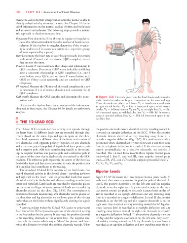
QRS width: Measure the QRS complex and determine if it is nor- n Figure 15-6 Electrode placement for limb leads and precordial
mal or wide. leads. Limb electrodes can be placed anywhere on the arms and legs.
Chest electrodes are placed as follows: V 1 5 fourth intercostal space
Determine the rhythm based on an analysis of the information at right sternal border; V 2 5 fourth intercostal space at left sternal
obtained in these steps. See Chapter 16 for details on arrhythmia border; V 3 5 halfway between V 2 and V 4 in a straight line; V 4 5 fifth
analysis. left intercostal space at midclavicular line; V 5 5 fifth left intercostal
space at anterior axillary line; V 6 5 fifth left intercostal space at mi-
daxillary line.
THE 12-LEAD ECG
The 12-lead ECG records electrical activity as it spreads through the positive electrode detects electrical activity traveling toward it,
the heart from 12 different leads that are recorded through elec- it records an upright deflection on the ECG. When the positive
trodes placed on the arms, legs, and specific spots on the chest. electrode detects electrical activity traveling away from it, it
Each lead represents a different view of the heart and consists of records a negative deflection (Fig. 15-7). If a positive electrode is
two electrodes with opposite polarity (bipolar), or one electrode positioned where electrical activity travels toward it and then away
and a reference point (unipolar). A bipolar lead has a positive pole from it, a diphasic deflection is recorded. If the electrical activity
and a negative pole, with each contributing equally to the record- travels perpendicular to a positive electrode, no activity is
ing. A unipolar lead has one positive pole and a reference pole in recorded. The 12-lead ECG records three bipolar frontal plane
the center of the chest that is algebraically determined by the ECG leads—lead I, lead II, and lead III; three unipolar frontal plane
machine. The reference pole represents the center of the electrical leads—aVR, aVL, and aVF; and six unipolar precordial leads: V 1 ,
field of the heart and has a zero potential, so only the positive pole V 2 , V 3 , V 4 , V 5 , and V 6 .
of a unipolar lead contributes to the tracing.
The standard 12-lead ECG consists of six limb leads that Bipolar Leads
record electrical activity in the frontal plane—traveling up/down
and right/left in the heart—and six precordial leads that record Figure 15-8A illustrates the three bipolar frontal plane leads. In
electrical activity in the horizontal plane—traveling anterior/pos- each lead, the camera represents the positive pole of the lead. In
terior and right/left. Limb leads are recorded by electrodes placed lead I, the positive electrode is on the left arm and the negative
on the arms and legs, whereas precordial leads are recorded by electrode is on the right arm. Any electrical activity in the heart
electrodes placed on the chest (Fig. 15-6). For convenience in that travels toward the positive electrode (camera lens) on the left
continuous bedside monitoring, arm electrodes can be placed on arm is recorded as an upright deflection and any traveling away
the shoulders and leg electrodes on the lower part of the rib cage from it is recorded as a negative deflection. In lead II, the positive
rather than on the limbs without significantly altering the signals electrode is on the left leg and the negative electrode is on the
recorded. right arm. Any electrical activity traveling toward the left leg elec-
A camera analogy makes the 12-lead ECG easier to understand. trode (camera lens) is recorded as an upright deflection and any
Each lead of the ECG represents a picture of the electrical activity traveling away from it toward the right arm electrode is recorded
in the heart taken by the camera. In any lead, the positive electrode as a negative deflection. In lead III, the positive electrode is on the
is the recording electrode or the camera lens. The negative elec- left leg and the negative electrode is on the left arm. Any electri-
trode tells the camera which way to “shoot” its picture and deter- cal activity coming toward the left leg electrode (camera lens) is
mines the direction in which the positive electrode records. When recorded as an upright deflection and any traveling away from it