
Page 330 - Cardiac Nursing
P. 330
/09
/09
1
6
/29
/29
0 P
0 P
M
1
0:3
0:3
0-3
32.
32.
30
30
0-3
xd
xd
6
q
q
q
M
t
ara
ara
p
p
t
In
c.
c.
a
a
In
g
g
e 3
Pa
Pa
g
A
A
p
e 3
06
06
p
LWBK340-c15_
LWB
K34
15_
0-c
p
LWB K34 0-c 15_ pp300-332.qxd 6/29/09 10:30 PM Page 306 Aptara Inc.
306 P A R T III / Assessment of Heart Disease
90
120 60
AVR AVL
V 1 150 30
V 2
180 0 I
V 3
V 4R V 4
V 5R V 5
150
30
V 6R V 6
120
90
60
V 7 III AVF II
V 8
V 9 A
90
120 60
A B AVR AVL
150 30
■ Figure 15-9 (A) Electrode placement for standard precordial
and right precordial leads. Only three right-sided leads are needed:
180 0 I
V
V 4R , right fifth intercostal space at midclavicular line; V 5R , right fifth
intercostal space at anterior axillary line; V 6R , right fifth intercostal
150
30
space at midaxillary line. (B) Electrode placement for posterior leads:
120
60
V V III
90 II
V 7 , left posterior axillary line; V 8 , tip of left scapula; V 9 , left border
V
of spine. All three are in the same horizontal plane of V 4 to V 6 . B AVF
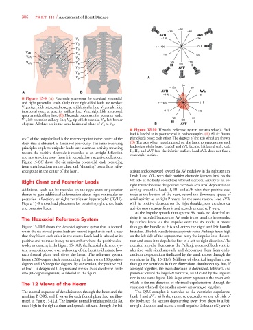
■ Figure 15-10 Hexaxial reference system (or axis wheel). Each
lead is labeled at its positive end in both examples. (A) All six frontal
end” of the unipolar lead is the reference point in the center of the plane leads bisect each other. The degrees of the axis wheel are shown.
chest that is obtained as described previously. The same recording (B) The axis wheel superimposed on the heart to demonstrate each
principles apply to unipolar leads: any electrical activity traveling lead’s view of the heart. Leads I and aVL face the left lateral wall, leads
toward the positive electrode is recorded as an upright deflection II, III, and aVF face the inferior surface. Lead aVR does not face a
ventricular surface.
and any traveling away from it is recorded as a negative deflection.
Figure 15-8C shows the six unipolar precordial leads recording
from their locations on the chest and “shooting” toward the refer-
ence point in the center of the heart. atrium and downward toward the AV node low in the right atrium.
Leads I and aVL, with their positive electrode (camera lens) on the
Right Chest and Posterior Leads left side of the body, record this leftward electrical activity as an up-
right P wave because the positive electrode sees atrial depolarization
Additional leads can be recorded on the right chest or posterior coming toward it. Leads II, III, and aVF, with their positive elec-
thorax to gain additional information about right ventricular or trode at the bottom of the heart, record the downward spread of
posterior infarction, or right ventricular hypertrophy (RVH). atrial activity as upright P waves for the same reason. Lead aVR,
Figure 15-9 shows lead placement for obtaining right chest leads with its positive electrode on the right shoulder, sees the electrical
and posterior leads. activity moving away from it and records a negative P wave.
As the impulse spreads through the AV node, no electrical ac-
The Hexaxial Reference System tivity is recorded because the AV node is too small to be recorded
by surface leads. As the impulse exits the AV node, it moves
Figure 15-10A shows the hexaxial reference system that is formed through the bundle of His and enters the right and left bundle
0
0
when the six frontal plane leads are moved together in such a way branches. The left bundle branch sprouts some Purkinje fibers high
that they bisect each other in the center. Each lead is labeled at its on the left side of the septum that carry the impulse into the sep-
positive end to make it easy to remember where the positive elec- tum and cause it to depolarize first in a left-to-right direction. The
trode, or camera, is. In Figure 15-10B, the hexaxial reference sys- electrical impulse then enters the Purkinje system of both ventric-
tem is superimposed over a drawing of the heart to illustrate how ular free walls simultaneously and depolarizes them from endo-
each frontal plane lead views the heart. The reference system cardium to epicardium (indicated by the small arrows through the
forms a 360-degree circle surrounding the heart with 180 positive ventricles in Fig. 15-11A). Millions of electrical impulses travel
degrees and 180 negative degrees. By convention, the positive end through the ventricles in three dimensions simultaneously, but, if
of lead I is designated 0 degrees and the six leads divide the circle averaged together, the main direction is downward, leftward, and
into 30-degree segments, as labeled in the figure. posterior toward the large left ventricle, as indicated by the large ar-
row in the same figure. This large arrow represents the mean axis,
The 12 Views of the Heart which is the net direction of electrical depolarization through the
ventricles when all the smaller arrows are averaged together.
The normal sequence of depolarization through the heart and the The QRS complex is recorded as the ventricles depolarize.
resulting P, QRS, and T waves for each frontal plane lead are illus- Leads I and aVL, with their positive electrodes on the left side of
trated in Figure 15-11A. The impulse normally originates in the SA the body, see the septum depolarizing away from them in a left-
node high in the right atrium and spreads leftward through the left to-right direction and record a small negative deflection (Q wave).