
Page 393 - Cardiac Nursing
P. 393
M
Pa
M
6 A
6 A
g
g
g
Pa
Pa
/09
/09
/09
/30
/30
2:1
2:1
1
1
1
ara
a
ara
t
t
c.
c.
In
a
In
69
69
69
e 3
e 3
p
p
p
A
A
6
0-c
87.
K34
q
q
87.
33
16_
33
3-3
3-3
q
LWB
LWB K34 0-c 16_ p p pp333-387.qxd 6/30/09 12:16 AM Page 369 Aptara Inc.
6
xd
xd
LWBK340-c16_
C HAPTER 1 6 / Arrhythmias and Conduction Disturbances 369
AV node
Fast pathway
Slow pathway
A
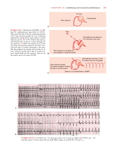
■ Figure 16-11 Mechanism of AVNRT. (A) The
dual AV nodal pathways responsible for AVNRT. PAC
The normal AV node is the fast conducting pathway
with a long refractory period; the slow conducting
pathway lies outside the AV node and has a shorter Fast pathway still refractory
refractory period. (B) A PAC finds the fast pathway from previous sinus beat
still refractory but is able to conduct through the
slow pathway. (C) When the impulse arrives at the
end of the slow pathway it finds the AV node recov-
ered and ready to conduct retrograde to the atria.
The slow pathway has already recovered due to its
short refractory period and is able to conduct the PAC conducts to ventricle via
same impulse back into the ventricle. This sets up B slow pathway = long PR interval
the reentry circuit and causes AVNRT.
Fast pathway recovers in time
to conduct impulse retrograde
Slow pathway already
recovered so able to conduct
impulse to ventricle again
Reentry circuit established = AVNRT
C
I aVR V1 V4
II aVL V2 V5
III aVF V3 V6
A A
I aVR V1 V4
II aVL V2 V5
III aVF V3 V6
B B
■ Figure 16-12 (A) AVNRT; rate—214 beats per minute. No P waves are visible. (B) AVNRT; rate—150
beats per minute. P waves distort the end of the QRS complex in leads II, III, aVF, and V 1–3 .