
Page 705 - Cardiac Nursing
P. 705
qxd
tar
49
04.
681
Ap
7
AM
P
g
/1/
p65
5-7
09
K34
0-c
28_
LWB K34 0-c 28_ p65 5-7 04. qxd 7 /1/ 09 9: 49 AM P a a g e e 681 Ap tar a a
LWBK340-c28_p655-704.qxd 7/1/09 9:9:49 AM Page 681 Aptara
LWB
C HAPTER 2 8 / Pacemakers and Implantable Defibrillators 681
When capture is lost in both ventricles, the QRS resumes its A
prepaced shape and width, usually a pattern of LBBB. VI VI VI V
Lead V 1 should logically be a good lead for evaluating ventricu-
lar capture in a biventricular pacemaker because of its ability to dif-
ferentiate RV from LV activation (see discussion of bundle-branch
block patterns in Chapter 15). Leads I and III or aVF are often used
to evaluate the QRS axis. It is recommended that a total of four 12-
lead ECGs should be recorded during implantation of a biventricu-
B
lar device: (1) QRS morphology during intrinsic conduction prior to VI VI VI V
any pacing, (2) paced QRS complexes during RV pacing alone, (3)
paced QRS complexes during LV pacing alone, and (4) paced QRS
37
complexes during biventricular capture. The lead or leads that best
show an obvious difference in QRS morphology among these four
pacing states should be used as the continuous bedside monitoring
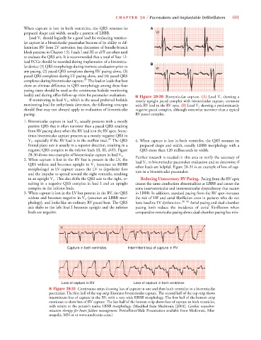
lead(s) and during office follow-up visits for pacemaker evaluation. ■ Figure 28-30 Biventricular capture. (A) Lead V 1 showing a
If monitoring in lead V 1 , which is the usual preferred bedside mostly upright paced complex with biventricular capture, common
monitoring lead for arrhythmia detection, the following concepts with RV lead in the RV apex. (B) Lead V 1 showing a predominantly
should (but may not always) apply to evaluation of biventricular negative paced complex, although somewhat narrower than a typical
pacing: RV paced complex.
1. Biventricular capture in lead V 1 usually presents with a mostly
positive QRS that is often narrower than a paced QRS resulting
from RV pacing alone when the RV lead is in the RV apex. Some-
times biventricular capture presents as a mostly negative QRS in
37
V 1 , especially if the RV lead is in the outflow tract. The QRS 4. When capture is lost in both ventricles, the QRS resumes its
frontal plane axis is usually in a superior direction, resulting in a prepaced shape and width, usually LBBB morphology with a
negative QRS complex in the inferior leads (II, III, aVF). Figure QRS more than 120 milliseconds in width.
28-30 shows two examples of biventricular capture in lead V 1 .
Further research is needed in this area to verify the accuracy of
2. When capture is lost in the RV but is present in the LV, the
lead V 1 in biventricular pacemaker evaluation and to determine if
QRS widens and becomes upright in V 1 (assumes an RBBB
other leads are helpful. Figure 28-31 is an example of loss of cap-
morphology) as LV capture causes the LV to depolarize first
ture in a biventricular pacemaker.
and the impulse to spread toward the right ventricle, resulting
in an upright V 1 . This also shifts the QRS axis to the right, re- Reducing Unnecessary RV Pacing. Pacing from the RV apex
sulting in a negative QRS complex in lead I and an upright creates the same conduction abnormalities as LBBB and causes the
complex in the inferior leads. same interventricular and intraventricular dysynchrony that occurs
3. When capture is lost in the LV but present in the RV, the QRS in LBBB. In addition, standard pacing from the RV apex increases
widens and becomes negative in V 1 (assumes an LBBB mor- the risk of HF and atrial fibrillation even in patients who do not
phology), and looks like an ordinary RV paced beat. The QRS have baseline LV dysfunction. 38–43 Atrial pacing and dual-chamber
axis shifts to the left; lead I becomes upright and the inferior pacing both reduce the incidence of atrial fibrillation when
leads are negative. compared to ventricular pacing alone; dual-chamber pacing has min-
V V V V
Capture in both ventricles Intermittent loss of capture in RV
Loss of capture in RV Loss of capture in both ventricles
■ Figure 28-31 Continuous strips showing loss of capture in one and then both ventricles in a biventricular
pacemaker. The first half of the top strip illustrates biventricular capture. The second half of the top strip shows
intermittent loss of capture in the RV, with a very wide RBBB morphology. The first half of the bottom strip
continues to show loss of RV capture. The last half of the bottom strip shows loss of capture in both ventricles,
with return to the patient’s native LBBB morphology. (Modified from Medtronic [2001]. Cardiac resynchro-
nization therapy for heart failure management. PowerPoint/Slide Presentation available from Medtronic, Min-
neapolis, MN or at www.medtronic.com.)