
Page 215 - ACCCN's Critical Care Nursing
P. 215
192 P R I N C I P L E S A N D P R A C T I C E O F C R I T I C A L C A R E
TABLE 9.2 Classification of heart murmurs using
the Levine scale 12
Grade 1 low intensity and difficult to hear
Grade 2 low intensity, but audible with a RA I
stethoscope but no palpable thrill LA
Grade 3 medium intensity and easily heard with a
stethoscope aV R aV L
Grade 4 loud and audible and with palpable thrill
Grade 5 very loud but cannot be heard outside the II III
praecordium and with palpable thrill
aV F
Grade 6 audible with the stethoscope away from
the chest
LL
or regurgitation at these locations. Murmurs are best
thought of as turbulent flow or vibrations associated with
the corresponding valve and can be of variable pitch.
17
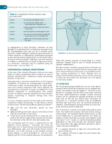
Specialist cardiac referral is indicated upon detection of FIGURE 9.12 Einthoven triangle formed by standard limb leads.
cardiac murmurs to differentiate pathological murmurs
as seen during valvular dysfunction or myocardial infarc-
tion from innocent systolic ‘high flow’ murmurs detected When the primary purpose of monitoring is to detect
in children or adolescents as a result of vigorous ventricu- ischaemic changes leads III and V3 usually present the
lar contraction. Murmurs may be classified using the optimal combination. 14
12
Levine scale, seen in Table 9.2.
The skin must be carefully prepared before electrodes are
CONTINUOUS CARDIAC MONITORING attached, as contact is required with the body surface and
In the case of the critically ill patient, there are two main poor contact will lead to inaccurate or unreadable record-
forms of cardiac monitoring, both of which are used to ings, causing interference or noise. Patients who are
generate essential data: continuous cardiac monitoring, sweaty need particular attention, and it may be necessary
and the 12-lead ECG. to shave the areas where the electrodes are to be placed
in very hairy people.
Internationally, a minimum standard for an ICU requires
availability of facilities for cardiovascular monitoring. 12-LEAD ECG
13
Continuous cardiac monitoring allows for rapid assess- The Dutch physiologist Einthoven was one of the first to
ment and constant evaluation with, when required, the
instantaneous production of paper recordings for more represent heart electrical conduction as two charged elec-
16
trodes, one positive and one negative. The body can be
detailed assessment or documentation into patient
records. In addition, practice standards for electrocardio- likened to a triangle, with the heart at its centre, and this
has been called Einthoven’s triangle. Cardiac electrical
graphic monitoring in hospital settings have been
established. 14 activity can be captured by placing electrodes on both
arms and on the left leg. When these electrodes are
It is now common practice for five leads to be used for connected to a common terminal with an indifferent
5
continuous cardiac monitoring, as this allows a choice electrode that stays near zero, an electrical potential is
of seven views. The five electrodes are placed as follows: 15 obtained. Depolarisation moving towards an active elec-
trode produces positive deflection.
● right and left arm electrodes: placed on each
shoulder; The 12-lead ECG consists of six limb leads and six chest
● right and left leg electrodes: placed on the hips or level leads. The limb leads examine electrical activity along a
with the lowest ribs on the chest; vertical plane. The standard bipolar limb leads (I, II, III)
● V-lead views can be monitored: for V1 place the elec- record differences in potential between two limbs by
trode at the 4th ICS, right of the sternum; for V6 place using two limb electrodes as positive and negative poles
the electrode at the 5th ICS, left mid-axillary line. (see Figure 9.12): Leads I, II, and III all produce positive
17
deflections on the ECG because the electrical current
The monitoring lead of choice is determined by the flows from left to the right and from upwards to down-
15
patient’s clinical situation. Generally, two views are wards. Placement should be:
better than one. V1 lead is best to view ventricular activity
and differentiate right and left bundle branch blocks; ● I = negative electrode in right arm and positive elec-
therefore, one of the channels on the bedside monitor trode in left arm
should display a V lead, preferably V1, and the other ● II = negative electrode in right arm and positive elec-
display lead II or III for optimal detection of arrhythmias. trode in left leg