
Page 518 - ACCCN's Critical Care Nursing
P. 518
Support of Renal Function 495
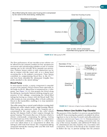
Blood-filled tubing fits inside outer housing and is compressed
by two cams to milk blood along, creating flow. Outer box housing of pump
Blood flow out of pump
Direction of rollers
Blood flow into pump
‘Cam’ of roller, which compresses
blood-filled tubing against outer housing
FIGURE 18.16 Roller pump for RRT.
The flow performance of any vascular-access catheter can
be affected by the patient’s position in bed, spontaneous Secondary IV line Syringe to adjust
movement and repositioning activities as part of routine Pressure sensing line blood level
nursing care in the critically ill for pressure-area preven-
tion. Catheter lumen outlet or inlet obstruction can be
due to contact with the vessel wall, or to a sharp bend
occurring due to the patient’s movement. These factors Air space and air–
blood interface
contribute to compromising blood flow in the EC, 42,77
and have been identified by ultrasound Doppler flow
probe attached to the circuit tubing. 79 Blood level
Blood Pump Direction of
In veno-venous modes, a pump component is essential blood flow
as part of the patient’s blood volume flows externally to
the body via the EC. Blood flow is maintained by a ‘roller
pump’ (see Figure 18.16), that propels the blood along
the tubing in a peristaltic fashion (milking along by com- Blood filter
pression of the tubing), compressing the blood-filled
tubing but having no contact with the blood itself. This
roller rotates at a rate providing a flow of fresh unfiltered
blood to the haemofilter, enabling it to clear metabolic
waste products.
The roller pump has a central anticlockwise rotating shaft FIGURE 18.17 Schematic of typical venous bubble trap design.
driving two roller wheels inside a rigid housing. Blood-
filled tubing sits stationary inside the housing and is
compressed by the outer surface of the roller wheels Venous Return Line Bubble Trap Chamber
during 180 degrees (half) of their rotation through the The purpose of this chamber is to prevent any gas bubbles
pump housing. This means that one of the two wheels is in the EC from entering the patient’s circulation by allow-
almost continuously compressing the tubing, moving ing them to rise to the top of a small, vertically positioned
blood forward out of the roller housing. The compression collection reservoir (see Figure 18.17). Venous pressure is
is not absolutely continuous, as there is a short time commonly measured via a tubing connection into the
(<0.5 sec) where there is no compression to allow the top of the venous chamber, and additional IV fluids can
tubing to refill with fresh blood. The compressed tubing be administered into this chamber via a secondary tube
reexpands behind the rotating roller and fills with fresh connection. The level of the blood in the chamber must
blood from the EC. be below the top, to prevent spillage into the pressure