Page 38 - E BOOK ENGINE MECHANICAL M2
P. 38

5. SERVICE POINTS OF 4B1 ENGINE COMPONENT


                                                       <Connecting Rod Bearing Installation>

                                                       1. When replacing a connecting rod bearing, select the
                                                       bearing corresponding to the crankshaft pin outside di-
                                                       ameter  according  to  the  crankshaft  pin  identification  in
                                                       the table below.

                                                       Crankshaft pin              Connecting rod bearing
                                                       Identification Journal di-  Identification  Identification
                                                       mark          ameter mm     color         mark
                                                       1             47.966 -      Black         1
                                                                     47.972
                                                       2             47.960 -      None or pur-  2
                                                                     47.966        ple
                                                       3             47.954 -      Green         3
                                                                     47.960


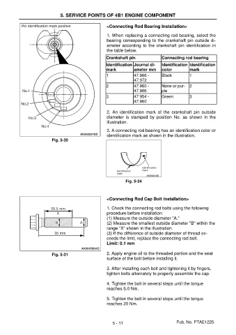
                                                       2.  An  identification  mark  of  the  crankshaft  pin  outside
                                                       diameter  is  stamped  by  position  No.  as  shown  in  the
                                                       illustration.
                                                       3. A connecting rod bearing has an identification color or
                                                       identification mark as shown in the illustration.
                           Fig. 5-30


                                                                Fig. 5-24


                                                       <Connecting Rod Cap Bolt Installation>

                                                       1. Check the connecting rod bolts using the following
                                                       procedure before installation:
                                                       (1) Measure the outside diameter "A."
                                                       (2) Measure the smallest outside diameter "B" within the
                                                       range "X" shown in the illustration.
                                                       (3) If the difference of outside diameter of thread ex-
                                                       ceeds the limit, replace the connecting rod bolt.
                                                       Limit: 0.1 mm

                           Fig. 5-31                   2. Apply engine oil to the threaded portion and the seat
                                                       surface of the bolt before installing it.

                                                       3. After installing each bolt and tightening it by fingers,
                                                       tighten bolts alternately to properly assemble the cap.

                                                       4. Tighten the bolt in several steps until the torque
                                                       reaches 5.0 Nm.

                                                       5. Tighten the bolt in several steps until the torque
                                                       reaches 20 Nm.


                                                          5 - 11                          Pub. No. PTAE1225
   33   34   35   36   37   38   39   40   41   42   43