Page 39 - E BOOK ENGINE MECHANICAL M2
P. 39

5. SERVICE POINTS OF 4B1 ENGINE COMPONENT


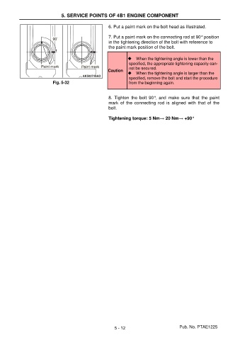
                                                       6. Put a paint mark on the bolt head as illustrated.

                                                       7. Put a paint mark on the connecting rod at 90° position
                                                       in the tightening direction of the bolt with reference to
                                                       the paint mark position of the bolt.


                                                                ◆  When the tightening angle is lower than the
                                                                 specified, the appropriate tightening capacity can-
                                                                 not be secured.
                                                       Caution
                                                                ◆  When the tightening angle is larger than the
                                                                 specified, remove the bolt and start the procedure
                           Fig. 5-32                             from the beginning again.


                                                       8.  Tighten  the  bolt  90°,  and  make  sure  that  the  paint
                                                       mark  of  the  connecting  rod  is  aligned  with  that  of  the
                                                       bolt.

                                                       Tightening torque: 5 Nm→ 20 Nm→ +90°


                                                          5 - 12                          Pub. No. PTAE1225
   34   35   36   37   38   39   40   41   42   43   44