
Page 132 - Learn To Program With Scratch
P. 132
try it out 5-3
Open the Ohm’s law simulator to run it, and study the scripts to understand how
it works . What do you think would happen if you added the command change
color effect by 25 at the end of the script for the Light sprite? Implement this
change to check your answer . What are some ways you could enhance this
application?
Demonstrating a Series Circuit
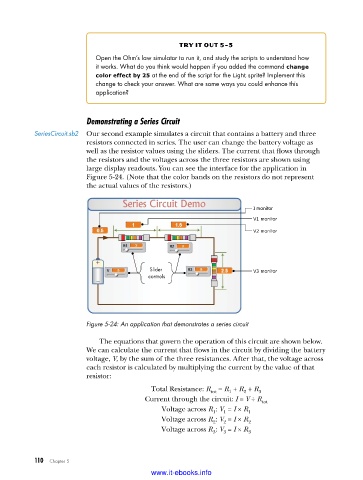
SeriesCircuit .sb2 Our second example simulates a circuit that contains a battery and three
resistors connected in series. The user can change the battery voltage as
well as the resistor values using the sliders. The current that flows through
the resistors and the voltages across the three resistors are shown using
large display readouts. You can see the interface for the application in
Figure 5-24. (Note that the color bands on the resistors do not represent
the actual values of the resistors.)
I monitor
try it out 5-4
V1 monitor
SeriesCircuit Open the series circuit simulator application and run it . Experiment with different
V2 monitor WithSwitch .sb2 values of R1, R2, R3, and V . Watch the calculated values of V1, V2, and V3 as
you drag the slider controls . What is the relationship between the voltage sum
(V1 + V2 + V3) and the battery voltage? What does this tell you about the voltage
relation in series circuits? You can make an interesting enhancement to the appli-
Slider V3 monitor cation by adding an image of a switch that opens or closes the circuit, as shown
controls below . When the switch is open, no current will flow in the circuit . Try to imple-
ment this change using the hints given below .
Script for the
Switch sprite
Figure 5-24: An application that demonstrates a series circuit Change how the main script calculates the current (I).
The equations that govern the operation of this circuit are shown below. Same as before
We can calculate the current that flows in the circuit by dividing the battery Switch sprite has
two costumes
voltage, V, by the sum of the three resistances. After that, the voltage across (On, Off). Switch if Off. Set current to 0.
each resistor is calculated by multiplying the current by the value of that
resistor:
Total Resistance: R = R + R + R 3
2
1
tot
Current through the circuit: I = V ÷ R tot
Voltage across R : V = I × R 1
1
1
Voltage across R : V = I × R 2
2
2
Voltage across R : V = I × R 3
3
3
110 Chapter 5
www.it-ebooks.info