
Page 71 - Digital Electronics by harish
P. 71
Select lines Outputs
A B Y 3 Y 2 Y 1 Y 0
0 0 0 0 0 D
0 1 0 0 D 0
1 0 0 D 0 0
1 1 D 0 0 0
Figure : Truth table of 1-to-4 demultiplexer
Y 0 = D
Y 1 = B D
Y 2 = A D
Y 3 = A B D
When A = 0 and B = 0, the first AND gate is enabled. Hence, the input D (0 or 1) will be
available at the output Y 0. When A = 0 and B = 1, the second AND gate is enabled and the
output Y 1will get the input D. When A = 1 and B = 0, we will get D at the output Y 2.
Similarly, Y 3 = D when A = 1 and B = 1.
IC 74139 is a dual 1-to-4 demultiplexer. It has two sets of 1-to-4 demultiplexer in a single
package. There are 16 pins in this IC.
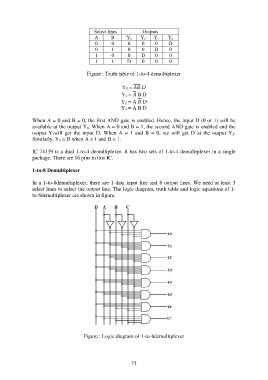
1-to-8 Demultiplexer
In a 1-to-8demultiplexer, there are 1 data input line and 8 output lines. We need at least 3
select lines to select the output line. The logic diagram, truth table and logic equations of 1-
to-8demultiplexer are shown in figure.
Figure : Logic diagram of 1-to-8demultiplexer
71