
Page 81 - Digital Electronics by harish
P. 81
3.1.5 T Flip-flop
The T (Toggle) Flip-flop is formed by connecting the J and K inputs of JKMS FF
together. (or) In a JKMS FF, when we make J = K, we will get a T FF. This is shown in
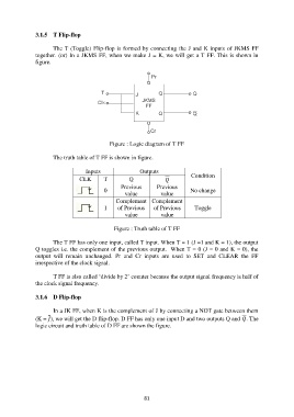
figure.
Figure : Logic diagram of T FF
The truth table of T FF is shown in figure.
Inputs Outputs
CLK T Q Condition
Previous Previous
0 No change
value value
Complement Complement
1 of Previous of Previous Toggle
value value
Figure : Truth table of T FF
The T FF has only one input, called T input. When T = 1 (J =1 and K = 1), the output
Q toggles i.e. the complement of the previous output. When T = 0 (J = 0 and K = 0), the
output will remain unchanged. Pr and Cr inputs are used to SET and CLEAR the FF
irrespective of the clock signal.
T FF is also called „divide by 2‟ counter because the output signal frequency is half of
the clock signal frequency.
3.1.6 D Flip-flop
In a JK FF, when K is the complement of J by connecting a NOT gate between them
(K = ), we will get the D flip-flop. D FF has only one input D and two outputs Q and . The
logic circuit and truth table of D FF are shown the figure.
81