
Page 77 - Digital Electronics by harish
P. 77
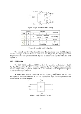
Figure : Logic circuit of CSR flip-flop

                                        Inputs              Outputs
                                 CLK      S      R        Q                Condition
                                                       Previous  Previous
                                          0      0      value      value     No change

                                          0      1        0          1         Reset
                                          1      0        1          0          Set
                                          1      1         Forbidden          Not used

                                           Figure : Truth table of CSR flip-flop

                       The inputs S and R will be allowed to enter the circuit only when the CLK input is
               present i.e. at logic „1‟. When there is no clock pulse (i.e. at logic „0‟), the flip-flop will retain
               the previous state. The operation of CSR flip-flop is similar to SR flip-flop when the clock
               signal is „1‟.

               3.1.3  JK Flip-flop

                       The NOT USED condition of SRFF i.e. S=1, R=1 condition is eliminated in the JK
               flip-flop. The condition J=1, K=1 is used to toggle the flip-flop. Toggling means, when the
               previous output is „0‟, the present output will be „1‟. Similarly, when the previous output is
               „1‟, the present output will be‟0‟.

                       JK FF has three inputs J, K and CLK and two outputs Q and . Preset (Pr) and Clear
               (Cr) inputs are also provided in the JK FF. The logic symbol, logic circuit diagram and truth
               table of JK FF are shown in figure.


                                             Figure : Logic symbol of JK FF


                                                           77