
Page 78 - Digital Electronics by harish
P. 78
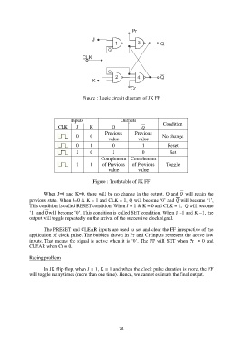
Figure : Logic circuit diagram of JK FF


                                    Inputs                  Outputs
                              CLK     J      K          Q                      Condition
                                                     Previous      Previous
                                      0      0        value          value       No change

                                      0      1          0              1           Reset
                                      1      0          1              0            Set
                                                   Complement  Complement
                                      1      1     of Previous    of Previous     Toggle
                                                      value          value

                                               Figure : Truth table of JK FF

                       When J=0 and K=0, there will be no change in the output. Q and  will retain the
               previous state. When J=0 & K = 1 and CLK = 1, Q will become „0‟ and  will become „1‟,
               This condition is called RESET condition. When J = 1 & K = 0 and CLK = 1,  Q will become
               „1‟ and will become „0‟. This condition is called SET condition. When J =1 and K =1, the
               output will toggle repeatedly on the arrival of the successive clock signal.

                       The PRESET and CLEAR inputs are used to set and clear the FF irrespective of the
               application of clock pulse. The bubbles shown in Pr and Cr inputs represent the active low
               inputs. That means the signal is active when it is „0‟. The FF will  SET when Pr  = 0 and
               CLEAR when Cr = 0.

               Racing problem

                       In JK flip-flop, when J = 1, K = 1 and when the clock pulse duration is more, the FF
               will toggle many times (more than one time). Hence, we cannot estimate the final output.


                                                           78