
Page 84 - Digital Electronics by harish
P. 84
3.2 Counters
The most important sequential circuits used in digital systems are
1) Counters and
2) Registers
A sequential logic circuit used for counting the number of pulses is known as a
counter. Counters are also used for measuring time and frequency.Flip-flops are the basic
elements used for designing the counter circuits. Basically there are two types of counters.
They are,
1. Asynchronous counter
2. Synchronous counter
3.2.1 Asynchronous counter
The asynchronous counter (ripple counter) is simple and straightforward in operation
and construction and requires minimum hardware. These counters are slow in operation. Each
flip-flop is triggered by the previous flip-flop and hence the counter has a cumulative settling
time. i.e. the flip-flops are connected in serial and hence these counters are also called serial
counters. In this type of counters, the triggers move through the flip-flop like a ripple in
water. Hence, these counters are also known as ripple counters.
3.2.1.1 Four bit binary asynchronous (ripple)UP counter
The logic diagram of 4-bit binary asynchronous UP counter is shown in figure. The
UP counter counts from 0000 to 1111.
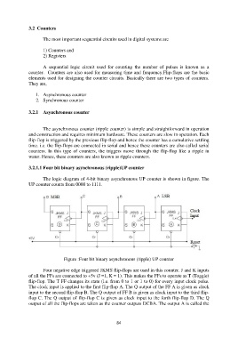
Figure :Four bit binary asynchronous (ripple) UP counter
Four negative edge triggered JKMS flip-flops are used in this counter. J and K inputs
of all the FFs are connected to +5v (J =1, K = 1). This makes the FFs to operate as T (Toggle)
flip-flop. The T FF changes its state (i.e. from 0 to 1 or 1 to 0) for every input clock pulse.
The clock input is applied to the first flip-flop A. The Q output of the FF A is given as clock
input to the second flip-flop B. The Q output of FF B is given as clock input to the third flip-
flop C. The Q output of flip-flop C is given as clock input to the forth flip-flop D. The Q
output of all the flip-flops are taken as the counter outputs DCBA. The output A is called the
84