
Page 87 - Digital Electronics by harish
P. 87
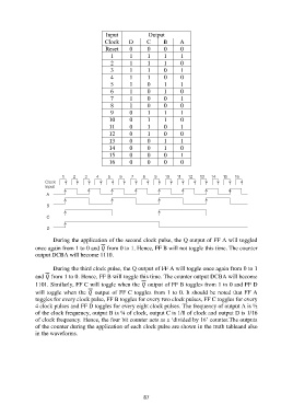
Input            Output
                                            Clock    D       C     B      A
                                            Reset     0      0      0     0
                                              1       1      1      1     1
                                              2       1      1      1     0
                                              3       1      1      0     1
                                              4       1      1      0     0
                                              5       1      0      1     1
                                              6       1      0      1     0
                                              7       1      0      0     1
                                              8       1      0      0     0
                                              9       0      1      1     1
                                             10       0      1      1     0
                                             11       0      1      0     1
                                             12       0      1      0     0
                                             13       0      0      1     1
                                             14       0      0      1     0
                                             15       0      0      0     1
                                             16       0      0      0     0


                       During the application of the second clock pulse, the Q output of FF A will toggled
               once again from 1 to 0 and  from 0 to 1. Hence, FF B will not toggle this time. The counter
               output DCBA will become 1110.

                       During the third clock pulse, the Q output of FF A will toggle once again from 0 to 1
               and  from 1 to 0. Hence, FF B will toggle this time. The counter output DCBA will become
               1101. Similarly, FF C will toggle when the  output of FF B toggles from 1 to 0 and FF D
               will toggle when the  output of FF C toggles from 1 to 0. It should be noted that FF A
               toggles for every clock pulse, FF B toggles for every two clock pulses, FF C toggles for every
               4 clock pulses and FF D toggles for every eight clock pulses. The frequency of output A is ½
               of the clock frequency, output B is ¼ of clock, output C is 1/8 of clock and output D is 1/16
               of clock frequency. Hence, the four bit counter acts as a „divided by 16‟ counter.The outputs
               of the counter during the application of each clock pulse are shown in the truth tableand also
               in the waveforms.


                                                           87