
Page 88 - Digital Electronics by harish
P. 88
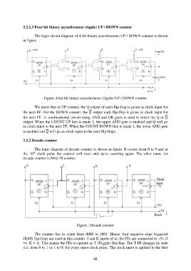
3.2.1.3 Four bit binary asynchronous (ripple) UP / DOWN counter

                       The logic circuit diagram of 4-bit binary asynchronous UP / DOWN counter is shown
               in figure.


                            Figure :Four bit binary asynchronous (ripple) UP / DOWN counter

                       We know that in UP counter, the Q output of each flip-flop is given as clock input for
               the next FF. For the DOWN counter, the  output each flip-flop is given as clock input for
               the next FF. A combinational circuit using AND and OR gates is used to select the Q or
               output. When the COUNT UP line is made 1, the upper AND gate is enabled and Q will go
               as clock input to the next FF. When the COUNT DOWN line is made 1, the lower AND gate
               is enabled and  will go as clock input to the next flip-flops.

               3.2.2 Decade counter

                       The logic diagram of decade counter is shown in figure. It counts from 0 to 9 and at
                      th
               the  10   clock  pulse  the  counter  will  reset  and  starts  counting  again.  The  other  name  for
               decade counter is Mod-10 counter.


                                                 Figure : Decade counter

                       The  counter  has  to  count  from  0000  to  1001.  Hence,  four  negative  edge  triggered
               JKMS flip-flops are used in this counter. J and K inputs of all the FFs are connected to +5v (J
               =1, K = 1). This makes the FFs to operate as T (Toggle) flip-flop. The T FF changes its state
               (i.e. from 0 to 1 or 1 to 0) for every input clock pulse. The clock input is applied to the first


                                                           88