Page 655 - CarrLaneCatalog_2019ed-c.pdf
P. 655

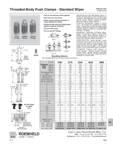
Threaded-Body Push Clamps - Standard Wiper                                                   7250 psi max
                                                                                                          Single acting

                                                • Can be mounted very close together  MOUNTING ON FIXTURE BASE: (Figure 1)
                                                                                    Fasten mounting block to fixture. Screw clamp
                                                • High force in a small size        into block. (See table below for recommended
                                                •  Mount using accessory brackets or   seating torque. Sealing washer provided).
                                                 screw directly into fixture        Block has male 37° fluid connection.
                                                                                    MANIFOLD MOUNTING: (Figure 2) Screw
                                                •  Positive stroke stop and long plunger   clamp into tapped hole prepared as shown
                                                 guide for superior reliability     below. Supply fluid through passages drilled
                                                                                    in fixture. Smallest size may be mounted with
                                                • Choice of five sizes              optional sealing nut. (Part no. CLR-508-TBA,
                                                **Do not use NPT fittings           7/8 Hex. x. 46 thick).
                                                                                    MOUNTING THROUGH FIXTURE WALL:
                                                                                    (Figure 3) (Through a tapped or bored hole).
                                                                                    Secure clamp using optional locknut or
                 Solid   Tapped   Swivel
                                                                                    mounting flange (two required for bored holes).
                Plunger  Plunger  Plunger                                           Feeder cap required for fluid connection.
                                                                                    CONSTRUCTION: Steel plunger, case-
                                                                                    hardened and ground. Positive stroke stop
                                                                                    prevents over-extending the plunger. Long
                                                                                    plunger guide provides support against side
                                                                                    loads. Do not load plunger in its retracted
                                                                                    position. Carbon steel body, black oxide finish.
                                                                                    PLUNGERS: Choose solid, tapped, or
                                                                                    swivel plunger. Tapped plunger accepts
                                                                                    contact bolts.  Swivel plunger distributes
                                                                                    force to prevent marring. Plunger extensions
                                                         Mounting Options           available by special order.
                                               See Threaded-Body Push Clamp accessories section


                                                      7250 psi
                                                                                                             1280            2270           3530            5530       8990

                                             Clamping
                                                                6000 psi                1100                         1900                        2900                          4500          7400
                                               force
                                                               5000 psi                 900                          1600                        2400                          3800                         6200
                                               (lbs)
                                                               4000 psi                 700                          1200                        1900                          3000          5000
                                                               3000 psi                 500                           900                         1400                          2300         3700
                                              Max. clamping force (lbs)               1310                     2340                        3650                          5700         9350
                                                  Stroke               .38                       .47                             .59                             .63              .78
                                               Fluid req’d (cu. in.)           .069                       .147                          .228                          .479            .981
                                               Piston area (sq. in.)          .175                       .312                          .487                          .760           1.247
                                              Force per 1000 psi (lbs)           175                        312                           487                           760            1247
                                              Max. oper. pressure (psi)            7500                       7500                         7500                         7500           7500
                                                   A                  7/8-14                      1-1/8-12                   1-1/4-16                   1-1/2-16            1-7/8-16
                                                   C1               1.50                        1.81                          2.19                          2.34            3.44
                                                   C2               1.78                        2.06                          2.59                           2.69            3.88
                                                   C3               1.80   2.09         2.73        2.86       —
                                                   D1                 .28                       .38                             .44                             .53                            .66
                                                   D2                 .56                       .66                             .81                             .88             1.09
                                                   D3                 .56                       .69                            . 97                           1.05               —
                                                  F dia               .47                       .63                             .78                           1.00             1.25
                                                   G                    .31                       .34                             .34                             .44               .50
                                                   H                 1.00                       1.19                          1.38                           1.69                          2.16
                                                              min.            .63                       .78                             .97                           1.13              1.66
                                                         I
                                                                     max            1.53                       1.41                          1.75                           1.81              2.75
                           See F&A section
                                                   J                    1/4-20x1/4               1/4-20x1/4              5/16-18x5/16   5/16-18x5/16            1/2-13x1/2
                             for contact
                                                  K dia                 .47                        .63                            .78                            1.00             1.25
                               bolts              L dia                 .19                       .19                             .19                            .19               .19
                                                   M                    .22                        .22                            .25                             .28               .34
                                                   R                    .75                        1.00                          1.25                          1.56             2.00
                                                   S                   .69                        .94                           1.69                          1.25             1.69
                                                   T                   .38                       .50                             .63                            .75               .94
                                                   U                   .28                       .28                             .41                            .41               —
                                               Seating torque (ft.-lbs)               29                        36                              43                             58               163
                                                Weight (lbs)             .18                      .33                             .48                             .48                2.13
                                              Part No., solid plunger            CLR-000-TB              CLR-100-TB             CLR-200-TB            CLR-300-TB         CLR-400-TB  14
                                              Part No., tapped plunger            CLR-001-TB              CLR-101-TB             CLR-201-TB            CLR-301-TB         CLR-401-TB
                                              Part No., swivel plunger            CLR-010-TB              CLR-110-TB             CLR-210-TB            CLR-310-TB            —
                      Manifold
                   Hole Preparations          Spare sealing washer            CLR-3000-840-SW         CLR-3000-179-SW        CLR-3000-180-SW      CLR-3000-843-SW     CLR-3000-181-SW
                                                                           Carr Lane Roemheld Mfg. Co.
                                                                                  Sales — Phone (314) 647-6200     Fax (314) 647-5736
                                                                         Engineering — Phone 1-800-827-2526     Web roemheld-usa.com
            8/18                                                                                                 653
   650   651   652   653   654   655   656   657   658   659   660