
Page 684 - CarrLaneCatalog_2019ed-c.pdf
P. 684
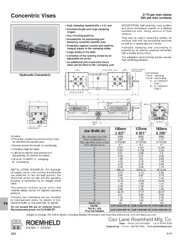
Concentric Vises                                                                      2175 psi max clamp
                                                                                            290 psi max unclamp

                                            •  High clamping repeatability ± 0.01 mm  DESCRIPTION: Self-centering vises position
                                            •  Constant length and large clamping   and clamp workpieces exactly on a defined
                                             ranges                             symmetrical axis, taking account of their
                                                                                contours.
                                            •  Any mounting position
                                                                                They may be used in machining centers, on
                                            •   Possibilities for positioning and
                                             fastening customer-specific jaws   machine tools and final processing machines
                                                                                as well as in special jigs and fixtures.
                                            •  Protection against coolant and swarf by
                                                                                Hydraulic clamping and unclamping is
                                             integral wipers in the clamping slides
                                                                                powered by an external pressure transmitter
                                            •  Large stroke of the slide
                                                                                with a double-acting circuit.
                                            •  Limitation of the opening stroke by an
                                             adjustable set screw               The adjustable synchronizing device ensures
                                                                                high centering precision.
                                            •  An additional pilot-controlled check
                                             valve can be fitted to the ‘clamping’ port
                                                                                                                  Connections:
              Hydraulic Concentric                                                              Port A - clamping
                                                                                                Port B - unclamping
                                                                                                      S1 -  oil lubrication
                                                                                                     slide 1
                                                                                                      S2 -  oil lubrication
                                                                                                     slide 2


                                                                            100mm        125mm        160mm
                                                        Jaw Width (A)
                                                                            3.937”       4.921”       6.299”
        Includes:                                     Max. clamping force (lbs)  3595      5620         8990
        •  Fitting key, positioning and mounting holes   Power stroke/slide (in.)  0.87    1.38         1.77
         for standard and special jaws               Max. operating pressure (psi)  2175/290  2175/290  2175/290
        •  Keyway across the length for positioning     Fluid required (cu.in.)  3.7        8.4          17
                                                              A              3.937         4.921        6.299
        •  Clamping edge for claws
                                                              A1             3.937         4.724        5.59
        •  Lubrication nipples and connections,               B               2.91         3.86          7.8
         respectively, for central lubrication.               B1              0.39         0.51         0.59
        •  Oil ports 1/4 BSPP, A - clamping,                  C               1.69          2.8         2.95
         B - unclamping                                       D               4.53         5.79         7.28
                                                              E               0.28         0.28         0.39
                                                              F               0.98         0.98         1.18
        INSTALLATION (EXAMPLE)  For hydraulic                 G              M8x12        M10x15       M12x18
        oil supply, pump units working intermittently         H               3.74         4.13         4.92
        are preferred. In the clamped position, the           H1              0.63         0.67         0.79
        directional valves are idle, and the operating        H1              1.02          1.1         1.34
        pressure is maintained by an integral check           L              15.35         19.69        23.62
        valve.                                                M               1.18         1.38         1.57
                                                              N               0.98         1.38         1.97
        Two pressure switches (pump control and
        machine safety) monitor the adjusted operating        N1              0.98         1.26         1.26
        pressure.                                             S              12.44         17.17        20.47
                                                              U               0.51         0.55         0.63
        Clamping and unclamping can be controlled             V               1.30         1.93         2.36
        by hand-operated valves, by selector or foot-         W               1.42         1.65         1.81
        operated switch or, fully automatic, by signals.   Weight (lbs)       49            86           150
   14
                                                            Part No.     CLRH-9-3542-0101-VS CLRH-9-3543-0101-VS CLRH-9-3544-0101-VS
        Do not exceed 300 psi on unclamp circuit.
        Recommended power unit CLR-886-EP.                Part No. with   CLRH-9-3542-0201-VS CLRH-9-3543-0201-VS CLRH-9-3544-0201-VS
                                                        Proximity Switches
                  Subject to change. For further details, including detailed dimensions and mounting instructions, visit roemheld-usa.com.
                                                                       Carr Lane Roemheld Mfg. Co.
                                                                              Sales — Phone (314) 647-6200     Fax (314) 647-5736
                                                                      Engineering — Phone 1-800-827-2526     Web roemheld-usa.com
        682                                                                                                  8/18