Page 279 - APPLIED PROCESS DESIGN FOR CHEMICAL AND PETROCHEMICAL PLANTS, Volume 1, 3rd Edition
P. 279

r-                                 Mechanical  Separations                                    249

                                                                tern, because the wire style, size, and material also affect the
                2.                                              value.  For  pressures  below  30  psig,  k  =  0.35  avg.,  then
                                                                above  30  psig,  k  value  decreases  with  pressure  with  an

                                                                Certain values  have  been found satisfactory for estimating
                  I                      I              I       approximate value of 0.30 at 250 psig and 0.275 at 800 psig.
                                                                systems described in Table 4-10 and Table 4-11.
                  I                                               For conditions  of high  liquid  loading,  use  caution  in
                1.  0                                           design.  Use  the  high  velocities  for  very  fine  mist  to
                                                       .4
                .9  0                                 I         remove  the  small  particles,  and  use  two  mesh  pads  in
                .8  0                                   ,       series with  the second mesh operating at a lower velocity
                .7  0                                I  a       Lo  remove  the  larger  drops  re-entrained  from  the  first
                                                   .4
                .60                                             mesh.  Systems  involving  high  viscosity  fluids  should  be
                                                 /��t.3         checked with the various manufacturers for their case his-
                .5  0                                           tory experience.  Lower k values are used for systems with
                                                � f  �P�2       high  vacuum,  high  viscosity  liquids,  low  surface  tension
                .40                             ,
                  I
                  !                          i                                      Table 4-10
                .30
             6'                                                              "k" Values for Knitted Mesh
             ::z::"'                     /Ji.
             E    !                             �                 Bottom of mesh at least 12 inches above liquid surface
             ;                                                  Service  Conditions     "k"      General  Type  Mesh
               .20
             "'t"                                               Clean  fluids,  moderate   0.35  to  0.36   Standard
             �                          '                       liquid load, fits 90%  of   0.35   High  Efficiency
             �                          '                       process  situations     0.25     Very  High  Efficiency
             ON                                                 High  viscosity,  dirty   0.40   Low  density  or
             I                                                  suspended  solids                Herringbone,  high
             (/)                     '                                                           through-put
             Q.J
             s:                    .4�-  j                      Vacuum  operations:
             �  .10                                              2"  Hg.  abs.          0.20     Standard  or
                                  I� 'II                         16"  Hg.  abs.         0.27     High  Efficiency
             g;  .09             II II                          Corrosive  Chemical     0.21     Plastic  coated  wire,
             �    .08                                                                            or  plastic  strand
                                II  II
             �   .D7          II II                             Compiled  from  various  manufacturer's  published  data.  Note:  k  values
             �  .06          II u                               for estimating pm·poses,  not final  design unless verified by  manufactur-
             (/)
             w                                                  er.  Unless stated,  all values based on stainless steel wire.
             a:                  ,
             c,  .05      II�
                   TYPEi  1i r                                          Variation of k with Disengaging Height*
               .04                                                                  Table 4-11

               .03                                                Disengaging Height Above  Mesh,  Inches  Allowable  k  Value

                    �� '//;'                                                    4                       0.15
                                                                                3 .......•..................  0.12
                                                                                                        0.22
               .02         TYPE'                                                5                       0.19
                                                                                6
                 I                                                              7 ........••....•...........  0.25
                 I  II
                 I              ' I                                             8                       0.29
                                                                                9
                                                                                                        0.32
                                                                                10
                                                                                11                      0.35
                                                                                                        0.38
                                                                                !2                      0.40
                                                                                13                      0.42
                               0.2     0.3    0.4   0.5  0.6   0.7              14                       0.43
                   K-factor,  V/[(pl - pv}lpv]"'  ft/sec (x 0.3048 = m/sec)
                                                                *By permission,  0.  H. York, Reference  (21).
                                                                Note:  Values based on  12 lb/cu  ft  wire  mesh.  Design  practice normally
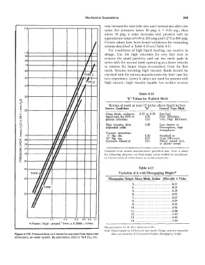
          Figure 4-17C. Pressure drop vs K-factor for standard York-Vane mist   does not exceed k of 0.4 even for higher disengaging height.
          eliminators, air-water system.  By permission,  Otto H. York Co.,  Inc.
   274   275   276   277   278   279   280   281   282   283   284