
Page 124 - Installation Manual - GenII DTS
P. 124
Accessories
Lanyard Stop Switch
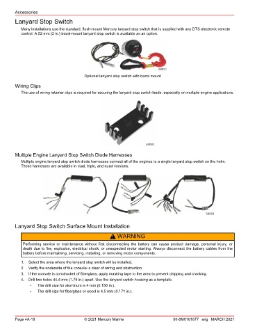
Many installations use the standard, flush‑mount Mercury lanyard stop switch that is supplied with any DTS electronic remote
control. A 52 mm (2 in.) bezel‑mount lanyard stop switch is available as an option.
69091
Optional lanyard stop switch with bezel mount
Wiring Clips
The use of wiring retainer clips is required for securing the lanyard stop switch leads, especially on multiple engine applications.
69092
Multiple Engine Lanyard Stop Switch Diode Harnesses
Multiple engine lanyard stop switch diode harnesses connect all of the engines to a single lanyard stop switch on the helm.
These harnesses are available in dual, triple, and quad versions.
69093
Lanyard Stop Switch Surface Mount Installation
! WARNING
Performing service or maintenance without first disconnecting the battery can cause product damage, personal injury, or
death due to fire, explosion, electrical shock, or unexpected motor starting. Always disconnect the battery cables from the
battery before maintaining, servicing, installing, or removing motor components.
1. Select the area where the lanyard stop switch will be installed.
2. Verify the underside of the console is clear of wiring and obstruction.
3. If the console is constructed of fiberglass, apply masking tape to the area to prevent chipping and cracking.
4. Drill two holes 44.4 mm (1.75 in.) apart. Use the lanyard switch housing as a template.
• The drill size for aluminum is 4 mm (0.156 in.).
• The drill size for fiberglass or wood is 4.5 mm (0.171 in.).
Page 4A-18 © 2021 Mercury Marine 90-8M0161677 eng MARCH 2021