
Page 125 - Installation Manual - GenII DTS
P. 125
Accessories
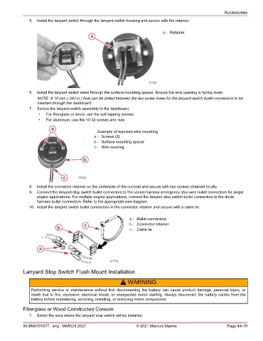
5. Install the lanyard switch through the lanyard switch housing and secure with the retainer.
a - Retainer
a
41521
6. Install the lanyard switch wires through the surface mounting spacer. Ensure the wire opening is facing down.
NOTE: A 10 mm (.393 in.) hole can be drilled between the two screw holes for the lanyard switch bullet connectors to be
inserted through the dashboard.
7. Secure the lanyard switch assembly to the dashboard.
• For fiberglass or wood, use the self‑tapping screws.
• For aluminum, use the 10‑32 screws and nuts.
a
Example of exposed wire mounting
a - Screws (2)
b - Surface mounting spacer
c - Wire opening
b
c 41523
8. Install the connector retainer on the underside of the console and secure with two screws obtained locally.
9. Connect the lanyard stop switch bullet connectors to the vessel harness emergency stop wire bullet connectors for single
engine applications. For multiple engine applications, connect the lanyard stop switch bullet connectors to the diode
harness bullet connectors. Refer to the appropriate wire diagram.
10. Install the lanyard switch bullet connectors in the connector retainer and secure with a cable tie.
a - Bullet connectors
c b - Connector retainer
b c - Cable tie
a
41774
Lanyard Stop Switch Flush Mount Installation
! WARNING
Performing service or maintenance without first disconnecting the battery can cause product damage, personal injury, or
death due to fire, explosion, electrical shock, or unexpected motor starting. Always disconnect the battery cables from the
battery before maintaining, servicing, installing, or removing motor components.
Fiberglass or Wood Constructed Console
1. Select the area where the lanyard stop switch will be installed.
90-8M0161677 eng MARCH 2021 © 2021 Mercury Marine Page 4A-19