
Page 130 - Installation Manual - GenII DTS
P. 130
Accessories
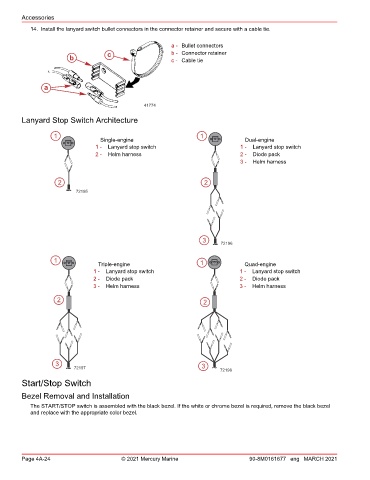
14. Install the lanyard switch bullet connectors in the connector retainer and secure with a cable tie.
a - Bullet connectors
c b - Connector retainer
b c - Cable tie
a
41774
Lanyard Stop Switch Architecture
1 1
Single-engine Dual-engine
1 - Lanyard stop switch 1 - Lanyard stop switch
2 - Helm harness 2 - Diode pack
3 - Helm harness
2 2
72195
3
72196
1
Triple-engine 1 Quad-engine
1 - Lanyard stop switch 1 - Lanyard stop switch
2 - Diode pack 2 - Diode pack
3 - Helm harness 3 - Helm harness
2 2
3
72197 3
72198
Start/Stop Switch
Bezel Removal and Installation
The START/STOP switch is assembled with the black bezel. If the white or chrome bezel is required, remove the black bezel
and replace with the appropriate color bezel.
Page 4A-24 © 2021 Mercury Marine 90-8M0161677 eng MARCH 2021