
Page 128 - Installation Manual - GenII DTS
P. 128
Accessories
7. Insert the two 50.8 mm (2.0 in.) 10‑32 screws through the lanyard switch and install the lanyard switch assembly to the
dashboard.
41781
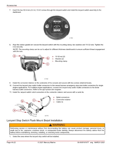
8. Align the rubber gasket and secure the lanyard switch with the mounting clamp, two washers and 10‑32 nuts. Tighten the
nuts securely.
NOTE: The mounting clamp can be cut to adjust for different thickness dashboards to ensure sufficient thread engagement
with the nuts.
a a - 10‑32 nut (2)
b b - Washer (2)
c - Mounting clamp
c
41782
9. Install the connector retainer on the underside of the console and secure with two screws obtained locally.
10. Connect the lanyard stop switch bullet connectors to the vessel harness emergency stop wire bullet connectors for single
engine applications. For multiple engine applications, connect the lanyard stop switch bullet connectors to the diode
harness bullet connectors. Refer to the appropriate wire diagram.
11. Install the lanyard switch bullet connectors in the connector retainer and secure with a cable tie.
a - Bullet connectors
c b - Connector retainer
b c - Cable tie
a
41774
Lanyard Stop Switch Flush Mount Bezel Installation
! WARNING
Performing service or maintenance without first disconnecting the battery can cause product damage, personal injury, or
death due to fire, explosion, electrical shock, or unexpected motor starting. Always disconnect the battery cables from the
battery before maintaining, servicing, installing, or removing motor components.
1. Select the area where the lanyard stop switch will be installed.
Page 4A-22 © 2021 Mercury Marine 90-8M0161677 eng MARCH 2021