
Page 126 - Installation Manual - GenII DTS
P. 126
Accessories
2. Verify the underside of the console is clear of wiring and obstruction.
3. Apply masking tape to the area to prevent chipping and cracking.
4. Drill two holes 44.4 mm (1.75 in.) apart. Use the lanyard switch housing as a template.
• The drill size for fiberglass or wood is 4.5 mm (0.171 in.).
5. Drill a 28.5 mm (1.125 in.) hole between the two holes.
6. Install the lanyard switch through the lanyard switch housing and secure with the retainer.
a - Retainer
a
41521
7. Install the rubber gasket over the lanyard switch wires.
8. Install the lanyard switch wires through the 28.5 mm (1.125 in.) hole in the dashboard.
a - Lanyard switch assembly
a b - Rubber gasket
c - 28.5 mm (1.125 in.) hole
b
c
41525
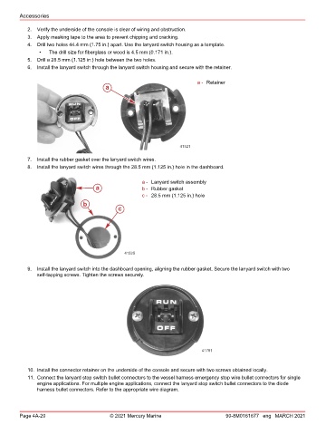
9. Install the lanyard switch into the dashboard opening, aligning the rubber gasket. Secure the lanyard switch with two
self‑tapping screws. Tighten the screws securely.
41781
10. Install the connector retainer on the underside of the console and secure with two screws obtained locally.
11. Connect the lanyard stop switch bullet connectors to the vessel harness emergency stop wire bullet connectors for single
engine applications. For multiple engine applications, connect the lanyard stop switch bullet connectors to the diode
harness bullet connectors. Refer to the appropriate wire diagram.
Page 4A-20 © 2021 Mercury Marine 90-8M0161677 eng MARCH 2021