
Page 243 - Fisika Terapan for Engineers and Scientists
P. 243
14.3 Levers and Pulleys 443
48 kg, and that the dimensions are as shown in the diagram. What force must the
muscles exert to balance the weight of the trunk when bent over horizontally?
SOLUTION: Figure 14.17 shows a “free-body” diagram for the backbone, with all
the forces acting on it. Since the weight w of the trunk acts at right angles to the
backbone, the lever arm for this weight is equal to the distance l 0.40 m between
the pivot and the center of mass of the trunk. The lever arm for the muscle is the
(small) distance l, which equals l 0.47 m sin 12 0.10 m. According to
Eq. (14.15), the force F exerted by the muscles then has magnitude
l l l 0.40 m
F F w Mg Mg 4.0 Mg
l l l 0.10 m
3
2
4.0 48 kg 9.81 m /s 1.9 10 N
This is a quite large force, 4.0 times larger than the weight of the trunk.
COMMENT: Bending over horizontally puts a severe stress on the muscles of the
back. Furthermore, it puts an almost equally large compressional stress on the back-
bone, pulling it hard against the sacrum. The stresses are even larger if you try to
lift a load from the floor while your body is bent over in this position. To avoid
damage to the muscles and to the lumbosacral disk, it is best to lift by bending the
knees, keeping the backbone vertical.
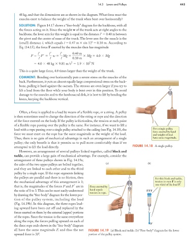
Often, a force is applied to a load by means of a flexible rope, or a string. A pulley
is then sometimes used to change the direction of the string or rope and the direction
of the force exerted on the body. If the pulley is frictionless, the tension at each point
of a flexible rope passing over the pulley is the same. For instance, if we want to lift a
load with a rope passing over a single pulley attached to the ceiling (see Fig. 14.18), the For a single pulley,
force exerted by hand
force we must exert on the rope has the same magnitude as the weight of the load. and weight of load
Thus, there is no gain of mechanical advantage in such an arrangement of a single have same magnitude.
pulley; the only benefit is that it permits us to pull more comfortably than if we
attempted to lift the load directly. FIGURE 14.18 A single pulley.
However, an arrangement of several pulleys linked together, called block and
tackle, can provide a large gain of mechanical advantage. For example, consider the
arrangement of three pulleys shown in Fig. 14.19a;
the axles of the two upper pulleys are bolted together, (a) (b)
and they are linked to each other and to the third
pulley by a single rope. If the rope segments linking
the pulleys are parallel and there is no friction, then For this block and tackle,
the mechanical advantage of this arrangement is 3; tension in rope F is only
that is, the magnitudes of the forces F and F are in Force exerted by one-third of the load F'.
the ratio of 1 to 3.This can be most easily understood hand equals FFF
tension in rope.
by drawing the “free-body” diagram for the lower por-
tion of the pulley system, including the load
(Fig. 14.19b). In this diagram, the three ropes lead-
ing upward have been cut off and replaced by the
forces exerted on them by the external (upper) portions
of the ropes. Since the tension is the same everywhere
along the rope, the forces pulling upward on each of
F'
the three rope ends shown in the “free-body” diagram
all have the same magnitude F, and thus the net FIGURE 14.19 (a) Block and tackle. (b) “Free-body” diagram for the lower
upward force is 3F. portion of the pulley system.