Page 357 - Clinical Application of Mechanical Ventilation
P. 357

Ventilator Waveform Analysis  323


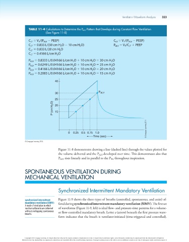
                          TABLE 11-4  Calculations to Determine the P ALV  Pattern that Develops during Constant Flow Ventilation
                                     (See Figure 11-8)

                          C  5 V /(P  2 PEEP)                                    C  5 V /(P  2 PEEP)
                                 T
                                                                                           ALV
                                    ALV
                                                                                   LT
                                                                                        T
                           LT
                          C  5 0.833 L/(30 cm H O 2 10 cm H O)                   P  5 V /C  1 PEEP
                                                           2
                           LT
                                                                                  ALV
                                               2
                                                                                        T
                                                                                           LT
                          C  5 0.833 L/20 cm H O
                                              2
                           LT
                          C  5 0.4166 L/cm H O
                                             2
                           LT
                          P  5 0.8333 L/0.04166 L/cm H O 1 10 cm H O 5 30 cm H O
                                                                                2
                           ALV
                                                                   2
                                                       2
                          P  5 0.6249 L/0.04166 L/cm H O 1 10 cm H O 5 25 cm H O
                                                                   2
                                                       2
                                                                                2
                           ALV
                          P  5 0.4166 L/0.04166 L/cm H O 1 10 cm H O 5 20 cm H O
                                                                                2
                                                       2
                                                                   2
                           ALV
                          P  5 0.2083 L/0.04166 L/cm H O 1 10 cm H O 5 15 cm H O
                                                                   2
                                                                                2
                                                       2
                           ALV
                                           40
                                           30                          P ALV
                                           25
                                          P (cm H 2 O)  20
                                           15
                                                                                                      © Cengage Learning 2014
                                                    0  0.25 0.5 0.75 1.0
                                                                    Time (sec)
                        © Cengage Learning 2014
                                             Figure 11-8 demonstrates drawing a line (dashed line) through the values plotted for
                                             the volume delivered and the P ALV  developed over time. This demonstrates also that
                                             P ALV  rises linearly and in parallel to the P  throughout inspiration.
                                                                               TA
                        SPONTANEOUS VENTILATION DURING
                        MECHANICAL VENTILATION


                                             Synchronized Intermittent Mandatory Ventilation


                        synchronized intermittent   Figure 11-9 shows the three types of  breaths (controlled, spontaneous, and assist) of-
                        mandatory ventilation (SIMV):   fered during synchronized intermittent mandatory ventilation (SIMV). The first set
                        A mode of ventilation in which
                        mechanical breaths are delivered   of waveforms (Figure 11-9, left) is ideal flow- and pressure-time patterns for a volume-
                        without overlapping spontaneous   or flow-controlled mandatory breath. Letter a (arrow) beneath the first pressure wave-
                        breaths.
                                             form indicates that the breath is ventilator-initiated (time-triggered and controlled).


                        Copyright 2013 Cengage Learning. All Rights Reserved. May not be copied, scanned, or duplicated, in whole or in part. Due to electronic rights, some third party content may be suppressed from the eBook and/or eChapter(s).
                      Editorial review has deemed that any suppressed content does not materially affect the overall learning experience. Cengage Learning reserves the right to remove additional content at any time if subsequent rights restrictions require it.
   352   353   354   355   356   357   358   359   360   361   362