
Page 363 - Clinical Application of Mechanical Ventilation
P. 363
Ventilator Waveform Analysis 329
(second example). These examples present what is known as true DRFWs (solid
lines), which means that flow descends from peak level to baseline (zero-end-flow).
The type of DRFW available for selection during VCV depends on the manu-
facturer. For example, the Puritan Bennett 840 ventilators offer a DRFW with an
end-flow of 5 L/min, and the Hamilton Medical Veolar provides the option of a
true DRFW, or one with an end-flow that is 50% of the initial peak flow, called a
50% DRFW.
The concepts presented here for Figure 11-13 are the same for the various types of
(Figure 11-13) During DRFWs. In the first example (left), a DRFW is superimposed over a CFW (dashed
time-limited ventilation, the I
time is unchanged when the lines) for comparison during time-limited ventilation, as offered by the Veolar in the
flow pattern is changed from CMV and SIMV modes. Inspiratory time (T ) is held constant (time-limited) when
constant flow to descending I
ramp flow. The same volume the flow waveform selection is adjusted from a CFW to a DRFW. Since the V is set
T
can only be maintained if the
peak flow of the descending and T is held constant, the average flow rate has to remain constant (V 5 Average
T
I
ramp flow is increased. Flow 3 T ). Average flow rate for a DRFW is 1/2 (Peak Flow 1 End-Flow). As dem-
I
onstrated in the first comparison of flow waves example, the area enclosed by the solid
and dashed line labeled a on the DRFW replaces the same area from the CFW area
labeled b. For the same volume to be delivered by either flow pattern within the same
“Time-limited” usage
in example: T I % is set on time period, transition from a CFW to a true DRFW on a time-limited ventilator
some ventilators. TCT and T I % requires the peak flow to be doubled.
determine the I time in sec
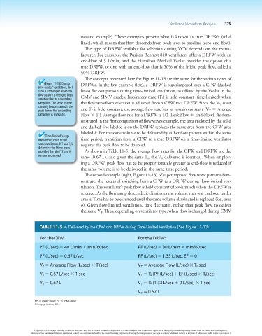
provided that the TCT and V T As shown in Table 11-5, the average flow rates for the CFW and DRFW are the
remain unchanged. same (0.67 L), and given the same T , the V delivered is identical. When employ-
I
T
ing a DRFW, peak flow has to be proportionately greater as end-flow is reduced if
the same volume is to be delivered in the same time period.
The second example (right, Figure 11-13) of superimposed flow wave patterns dem-
onstrates the results of switching from a CFW to a DRFW during flow-limited ven-
tilation. The ventilator’s peak flow is held constant (flow-limited) when the DRFW is
selected. As the flow ramp descends, it eliminates the volume that was enclosed under
area a. Time has to be extended until the same volume eliminated is replaced (i.e., area
b). Given flow-limited ventilation, time fluctuates, rather than peak flow, to deliver
the same V . Thus, depending on ventilator type, when flow is changed during CMV
T
TABLE 11-5 V T Delivered by the CFW and DRFW during Time-Limited Ventilation (See Figure 11-13)
For the CFW: For the DRFW:
PF (L/sec) 5 40 L/min 3 min/60sec PF (L/sec) 5 80 L/min 3 min/60sec
PF (L/sec) 5 0.67 L/sec PF (L/sec) 5 1.33 L/sec, EF 5 0
V 5 Average Flow (L/sec) 3 T (sec) V 5 Average Flow (L/sec) 3 T (sec)
I
T
I
T
V 5 0.67 L/sec 3 1 sec V 5 ½ (PF (L/sec) 1 EF (L/sec) 3 T (sec)
T
T
I
V 5 0.67 L V 5 ½ (1.33 L/sec 1 0 L/sec) 3 1 sec
T
T
V 5 0.67 L
T
PF 5 Peak flow; EF 5 end-flow.
© Cengage Learning 2014
Copyright 2013 Cengage Learning. All Rights Reserved. May not be copied, scanned, or duplicated, in whole or in part. Due to electronic rights, some third party content may be suppressed from the eBook and/or eChapter(s).
Editorial review has deemed that any suppressed content does not materially affect the overall learning experience. Cengage Learning reserves the right to remove additional content at any time if subsequent rights restrictions require it.