
Page 501 - Clinical Application of Mechanical Ventilation
P. 501
Procedures Related to Mechanical Ventilation 467
Some bubbling from the long tube is normal as long as there is air in the pleural
space. If there is no bubbling, either there is an obstruction or there is no more air
in the pleural space.
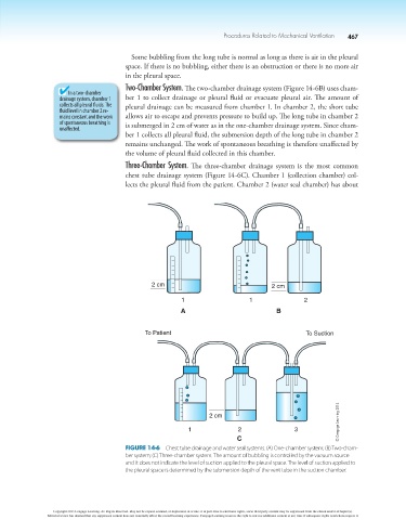
Two-Chamber System. The two-chamber drainage system (Figure 14-6B) uses cham-
In a two-chamber
drainage system, chamber 1 ber 1 to collect drainage or pleural fluid or evacuate pleural air. The amount of
collects all pleural fluids. The pleural drainage can be measured from chamber 1. In chamber 2, the short tube
fluid level in chamber 2 re-
mains constant and the work allows air to escape and prevents pressure to build up. The long tube in chamber 2
of spontaneous breathing is is submerged in 2 cm of water as in the one-chamber drainage system. Since cham-
unaffected.
ber 1 collects all pleural fluid, the submersion depth of the long tube in chamber 2
remains unchanged. The work of spontaneous breathing is therefore unaffected by
the volume of pleural fluid collected in this chamber.
Three-Chamber System. The three-chamber drainage system is the most common
chest tube drainage system (Figure 14-6C). Chamber 1 (collection chamber) col-
lects the pleural fluid from the patient. Chamber 2 (water seal chamber) has about
2 cm 2 cm
1 1 2
A B
To Patient To Suction
© Cengage Learning 2014
2 cm
1 2 3
C
Figure 14-6 Chest tube drainage and water seal systems. (A) One-chamber system; (B) Two-cham-
ber system; (C) Three-chamber system. The amount of bubbling is controlled by the vacuum source
and it does not indicate the level of suction applied to the pleural space. The level of suction applied to
the pleural space is determined by the submersion depth of the vent tube in the suction chamber.
Copyright 2013 Cengage Learning. All Rights Reserved. May not be copied, scanned, or duplicated, in whole or in part. Due to electronic rights, some third party content may be suppressed from the eBook and/or eChapter(s).
Editorial review has deemed that any suppressed content does not materially affect the overall learning experience. Cengage Learning reserves the right to remove additional content at any time if subsequent rights restrictions require it.