
Page 502 - Clinical Application of Mechanical Ventilation
P. 502
468 Chapter 14
2 cm of water in it and functions as a water seal. The water level in chamber 3
The water level in (suction chamber) regulates the amount of suction in the three-chamber system.
chamber 3 (suction chamber)
regulates the amount of For example, a suction level of 215 cm H O can be achieved by adding sterile water
2
suction in the three-chamber into this chamber to a height of 15 cm H O. A low suction level (210 to 220 cm
system. 2
H O) is recommended for the chest tube drainage system.
2
Under normal working condition, the vacuum draws air into the fluid through the
venting tube in chamber 3, causing a constant slow bubbling effect. Too much bub-
bling means the vacuum level is set too high. The setting of wall vacuum and the
The setting of wall
vacuum and the amount of amount of bubbling do not reflect the level of suction applied to the pleural space. The
bubbling in chamber 3 do not level of suction applied to the pleural space is determined by the submersion depth
reflect the level of suction ap-
plied to the pleural space. of the venting tube in suction chamber 3. For this reason, the water level in suction
chamber 3 must be monitored and kept at the appropriate level in order to maintain
a desired vacuum level (from 210 to 220 cm H O). Evaporative water loss will lower
2
the submersion depth and decrease the suction level.
The one- and two-column drainage systems drain fluid by gravity. If suction is
desired, a three-column system must be used. Figure 14-7 shows a typical chest tube
drainage system that combines all three chambers in one unit.
© Cengage Learning 2014
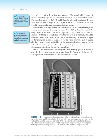
Figure 14-7 A typical chest tube drainage system that combines all three columns [suction
control (A), water seal (B), and collection (C)] in one unit. In some drainage systems, the cap for the
water seal column has a pressure relief valve which is closed under normal suction and opens in
case of excessive pressure caused by blocked suction source or obstructed suction tubing. This
feature prevents excessive pressure being transmitted to the chest tube and pleural space.
Copyright 2013 Cengage Learning. All Rights Reserved. May not be copied, scanned, or duplicated, in whole or in part. Due to electronic rights, some third party content may be suppressed from the eBook and/or eChapter(s).
Editorial review has deemed that any suppressed content does not materially affect the overall learning experience. Cengage Learning reserves the right to remove additional content at any time if subsequent rights restrictions require it.