
Page 162 - Basic Course
P. 162
KNX BASIC COURSE
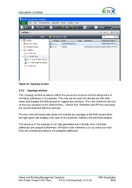
Figure 20: Topology window
2.4.3 Topology window
The Topology window is used to define the actual bus structure and the assignment of
individual addresses to the devices. This view can be used simultaneously with other
views and displays the KNX project as regards bus structure. The view shows the devices
as they are assigned to the different lines. Twisted Pair, Powerline and IP lines and areas
are represented with different symbols.
The tree view (left-hand side) shows the existing bus topology of the KNX project while
the right-hand side displays a list view of the elements marked in the left-hand window.
The structure of the topology is normally generated automatically when individual
addresses are assigned elsewhere. All higher-order elements such as areas and main
lines are inserted according to the assigned addresses.
Home and Building Management Systems KNX Association
KNX Project Design ETS4: Basic ETS4_Planning basic_E1212c 27/41