
Page 90 - Digital Electronics by harish
P. 90
3.2.3 Modulo–N counter
We know that the 4-bit binary asynchronous as well as synchronous counters resets to
th
0000 and starts counting again in every 16 clock pulse automatically. This is called „divide
th
by 16‟ counter or „mod-16‟ counter. i.e. a mod-N counter resets in every N clock pulse. We
can design any mod-N counter using an additional NAND gate in the counter circuit to reset
th
th
the counter in every N clock pulse. In simply says, a MOD-N counter resets at N clock
pulse.
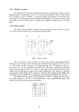
3.2.3.1 Mod-3 counter
The logic diagram of Mod-3 counter is shown in figure. It counts from 0 to 2 and at
rd
the 3 clock pulse the counter will reset and starts counting again.
Figure : Mod-3 counter
The counter has to count from 00 to 10. Hence, two negative edge triggered JKMS
flip-flops are used in this counter. J and K inputs of all the FFs are connected to +5v (J =1, K
= 1). This makes the FFs to operate as T (Toggle) flip-flop. The T FF changes its state (i.e.
from 0 to 1 or 1 to 0) for every input clock pulse. The clock input is applied to the first flip-
flop A. The Q output of the FF A is given as clock input to the second flip-flop B. The Q
output of all the flip-flops are taken as the counter outputs BA. The output A is called the
Least Significant Bit (LSB) and the output B is called the Most Significant Bit (MSB). The
CLEAR (Cr) input of all the FFs are connected to ground through the Master Reset switch.
rd
We need to reset the counter at 3 clock pulse i.e. at BA = 11. Hence, we have to reset
the counter when B = 1 and A = 1. The NAND gate is used to apply RESET signal. The
inputs for the NAND gate are taken from B and A.
Input Output
Clock B A
Reset 0 0
1 0 1
2 1 0
3 0 0
4 0 1
90