
Page 93 - Digital Electronics by harish
P. 93
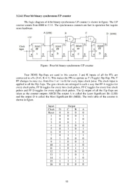
3.2.4.1 Four bit binary synchronous UP counter

                       The logic diagram of 4-bit binary synchronous UP counter is shown in figure. The UP
               counter counts from 0000 to 1111. The synchronous counters are fast in operation but require
               more hardware.


                                     Figure : Four bit binary synchronous UP counter


                       Four  JKMS  flip-flops  are  used  in  this  counter.  J  and  K  inputs  of  all  the  FFs  are
               connected to +5v (J =1, K = 1). This makes the FFs to operate as T (Toggle) flip-flop. The T
               FF changes its state (i.e. from 0 to 1 or 1 to 0) for every input clock pulse. The clock input is
               applied to all the flip-flops. The gate circuits are arranged in such a way that FF A toggles for
               every clock pulse, FF B toggles for every two clock pulses, FF C toggles for every four clock
               pulses and FF D toggles for every eight clock pulses. The Q output of all the flip-flops are
               taken as the counter outputs ABCD.The output A is called the Least Significant Bit (LSB)
               and the output D is called the Most Significant Bit (MSB). The truth table of the counter is
               shown in figure.

                                            Input            Output
                                            Clock    D       C     B      A
                                            Reset     0      0      0     0
                                              1       0      0      0     1
                                              2       0      0      1     0
                                              3       0      0      1     1
                                              4       0      1      0     0
                                              5       0      1      0     1
                                              6       0      1      1     0
                                              7       0      1      1     1
                                              8       1      0      0     0
                                              9       1      0      0     1
                                             10       1      0      1     0
                                             11       1      0      1     1
                                             12       1      1      0     0
                                             13       1      1      0     1
                                             14       1      1      1     0
                                             15       1      1      1     1
                                             16       0      0      0     0


                                                           93