
Page 97 - Digital Electronics by harish
P. 97
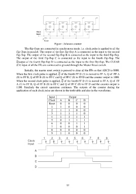
Figure : Johnson counter

                       The flip-flops are connected in synchronous mode. i.e. clock pulse is applied to all the
               flip-flops in parallel. The output of the first flip-flop A is connected as the input to the second
               flip-flop. The output of the second flip-flop B is connected as the input to the third flip-flop.
               The  output  of  the  third  flip-flop  C  is  connected  as  the  input  to  the  fourth  flip-flop.  The
               output of the fourth flip-flop D is connected as the input to the first flip-flop. The CLEAR
               (Cr) input of all the FFs are connected to ground through the Master Reset switch.

                       Initially, the master reset switch is pressed to clear all the FFs so that ABCD is 0000.
               When the first clock pulse is applied,  of the fourth FF D (1) is moved to FF A, Q of  FF A
               (0) to FF B, Q of FF B (0) to FF C and Q of FF C (0) to FF D and the counter output is 1000.
               When the second clock pulse is applied,  of the fourth FF D (1) is moved to FF A, Q of  FF
               A (1) to FF B, Q of FF B (0) to FF C and Q of FF C (0) to FF D and the counter output is
               1100.  Similarly  the  circuit  operation  continues.  The  outputs  of  the  counter  during  the
               application of each clock pulse are shown in the truth table and also in the waveforms.

                                            Input            Output
                                            Clock    A       B     C      D
                                            Reset     0      0      0     0
                                              1       1      0      0     0
                                              2       1      1      0     0
                                              3       1      1      1     0
                                              4       1      1      1     1
                                              5       0      1      1     1
                                              6       0      0      1     1
                                              7       0      0      0     1
                                              8       0      0      0     0
                                              9       1      0      0     0


                                                           97