
Page 290 - ACCCN's Critical Care Nursing
P. 290
Cardiac Rhythm Assessment and Management 267
TABLE 11.3 Pacemaker controls and settings
Control Function
Base rate Sets the rate at which the pacemaker will discharge: pacing occurs at this rate unless the patient’s own rate is faster
and is sensed by the pacemaker. Typically set at 60–100/min.
Ventricular output The size, or strength, of the stimulus delivered to the ventricles. In temporary devices this is an adjustable current
(measured in milliamperes [mA]). Output is increased until capture (successful stimulation) is achieved. The
minimum current required to achieve capture is termed the output threshold. Impulses delivered below the
threshold value will not capture the myocardium. Temporary pacemakers have an adjustable output range of
0.1–25 mA.
Atrial output The size or strength of the stimulus delivered to the atria. Range 0.1 to 20 mA.
Atrial and ventricular Not adjustable on all devices. Allows adjustment of the duration for which the pacemaker output is applied to the
pulse width myocardium. Selectable range typically 1.0–2.0 milliseconds (msec) in 0.25 msec increments. Increasing the pulse
width enhances ability to gain capture.
Atrioventricular delay The interval between the delivery of the atrial and ventricular pacing stimuli. Normally this is set in the same range
as normal P–R intervals (between 0.12 and 0.20 sec).
Sensitivity Affects the ability of the pacemaker to detect the presence of spontaneous cardiac activity. Sensitivity settings can
be adjusted between 1.0 and 20 millivolts (mV). Set at 1.0 mV the device is very sensitive (able to sense small
electrical signals from the heart). Set at higher values, the device becomes less sensitive (higher voltage signals
required to be detected), with the risk that QRS complexes or P waves will not be sensed.
TABLE 11.4 Pacemaker terminology 56
Antitachyarrhythmia
Chamber paced Chamber sensed Response to sensing Programmable functions functions
O, none O, none O, none O, none O, none
A, atrium A, atrium T, triggered P, simple programmable P, pacing
V, ventricle V, ventricle I, inhibited M, multi-programmable S, shock
D, dual (A & V) D, dual (A & V) D, dual (T & I) C, communicating D, dual (P & S)
R, rate modulation
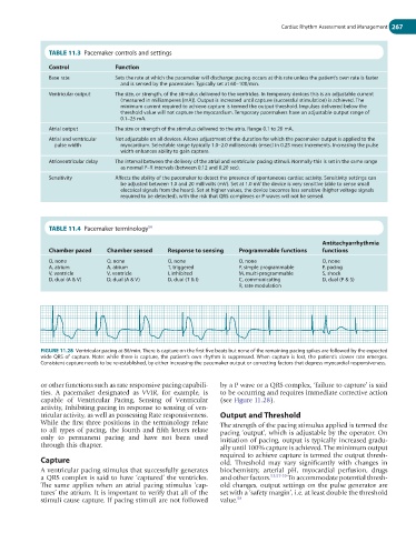
FIGURE 11.28 Ventricular pacing at 86/min. There is capture on the first five beats but none of the remaining pacing spikes are followed by the expected
wide QRS of capture. Note: while there is capture, the patient’s own rhythm is suppressed. When capture is lost, the patient’s slower rate emerges.
Consistent capture needs to be re-established, by either increasing the pacemaker output or correcting factors that depress myocardial responsiveness.
or other functions such as rate responsive pacing capabili- by a P wave or a QRS complex, ‘failure to capture’ is said
ties. A pacemaker designated as VVIR, for example, is to be occurring and requires immediate corrective action
capable of Ventricular Pacing, Sensing of Ventricular (see Figure 11.28).
activity, Inhibiting pacing in response to sensing of ven-
tricular activity, as well as possessing Rate responsiveness. Output and Threshold
While the first three positions in the terminology relate The strength of the pacing stimulus applied is termed the
to all types of pacing, the fourth and fifth letters relate pacing ‘output’, which is adjustable by the operator. On
only to permanent pacing and have not been used initiation of pacing, output is typically increased gradu-
through this chapter. ally until 100% capture is achieved. The minimum output
required to achieve capture is termed the output thresh-
Capture old. Threshold may vary significantly with changes in
A ventricular pacing stimulus that successfully generates biochemistry, arterial pH, myocardial perfusion, drugs
a QRS complex is said to have ‘captured’ the ventricles. and other factors. 53,57-59 To accommodate potential thresh-
The same applies when an atrial pacing stimulus ‘cap- old changes, output settings on the pulse generator are
tures’ the atrium. It is important to verify that all of the set with a ‘safety margin’, i.e. at least double the threshold
stimuli cause capture. If pacing stimuli are not followed value. 58